3 - 3
(2) Tuning controls (MAIN unit)
A motor driver (IC15) rotates the tuning motors (MF1, MF2)
to obtain a low SWR.
(3) Tuning relays (C-NET, L-NET and H-NET boards)
According to the operating frequency band and antenna
condition, tuning relays select the capacitors and coils.
3-3 PROTECTION CIRCUITS
3-3-1 GENERAL
The IC-PW1 has two protection systems. One system
bypasses the power amplifier, and the other system shuts
down the internal power supply activation.
Protection activates when:
• a mismatched frequency band signal is transmitted.
• the ALC control level exceeds the control range.
• the power level balance between the 4 PA units becomes
unbalanced.
• the output voltage of the internal power supply (VD)
exceeds 55 V DC.
• the current of the power amplifiers (ID) exceeds 50 A.
• the heatsink temperature of the power amplifier exceeds
+100˚C (212˚F).
• the applied AC voltage exceeds the specified value.
The main CPU controls the THROUGH/AMP switch and
internal power supply operation.
3-3-2 ALC CIRCUIT (MAIN UNIT)
The ALC (Automatic Level Control) circuit automatically lim-
its RF output power by controlling the input level of the
exciter.
(1) FOR-ALC
The detected “FOR” voltage signal from the SWR detector
circuit (FILTER unit; D15, D16, L22) is op-amplified at IC1a
then applied to the ACC2 socket (JACK1 unit; J5, pin 5) via
the ALC adjustment pot (JACK1 unit; R1) and ALC2 jack
(JACK2 unit; J7).
(2) I
D-ALC
In the IC-PW1, internal power supply voltage (ID) is used for
ID-ALC. The power supply voltage (ID) is amplified at the op-
amplifier (IC1c), then applied to the ACC2 socket.
(3) SWR-ALC
SWR-ALC protects the power amplifiers (PA1–PA4 boards;
Q1a/b) when SWR worsens and when dielectric break-
down/discharge from excessive voltage rises.
The detected “REF” voltage signal from the SWR detector
circuit (FILTER unit; D15, D16, L22) is op-amplified at the
SWR/DRIVE amplifier (IC1b) then applied to the ACC2
socket (JACK1 unit; J5, pin 5).
(4) DRV-ALC
DRV-ALC activates when the exciter input exceeds 120 W
to protect the power amplifiers. The op-amplified “REF” sig-
nal at the SWR/DRIVE amplifier (IC1b) is used for operation.
However, the limiter circuit on the SPRITR unit (D4, D5) is
activated for momentary excessive input such as leading
edge power, etc.
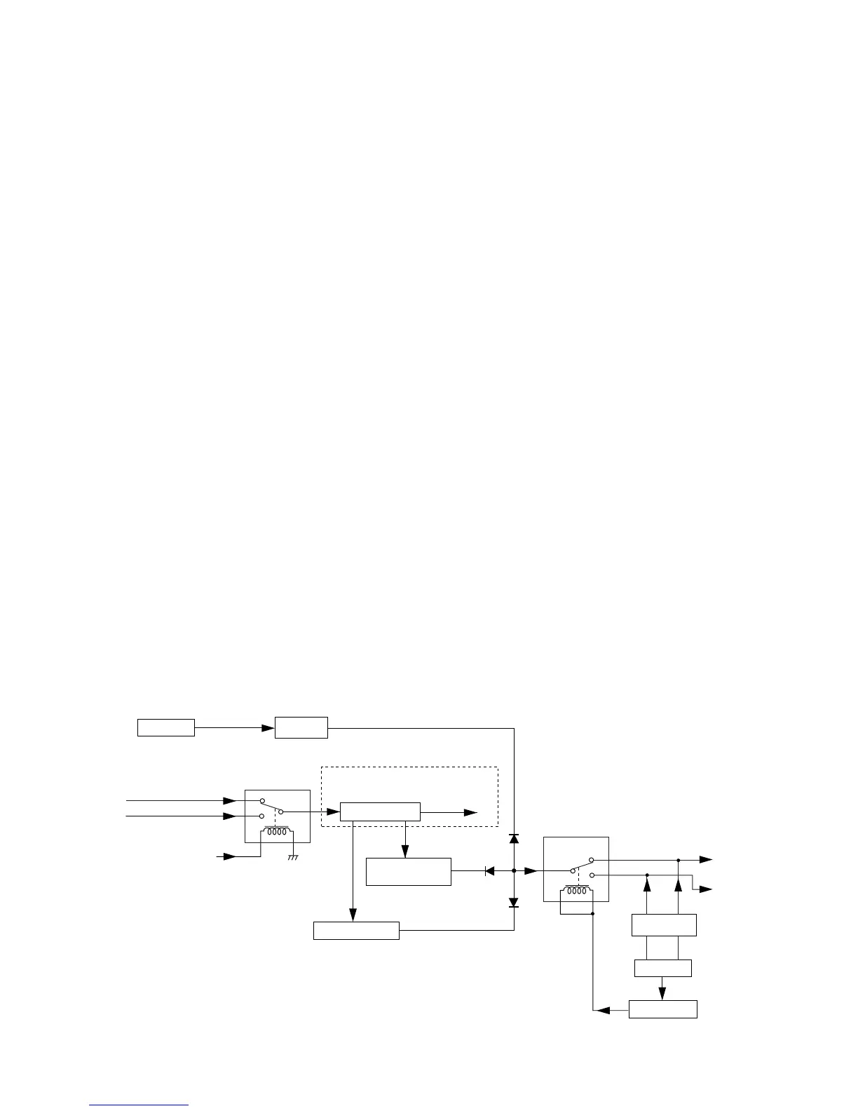
3-3-3 DRIVING POWER DETECTOR CIRCUIT
(SPLITR AND MAIN UNITS)
A portion of the attenuated input power from the exciter input
switching circuit (SPLITR unit; RL1) is divided by R7 and R8,
and then rectified at D3, R2 and C5 for conversion to DC
voltages. The rectified DC voltages are applied to the drive
amplifier (MAIN unit; IC21a/b). The amplified DC voltages
are applied to the main CPU (MAIN unit; IC26)
 Loading...