INTRODUCTION
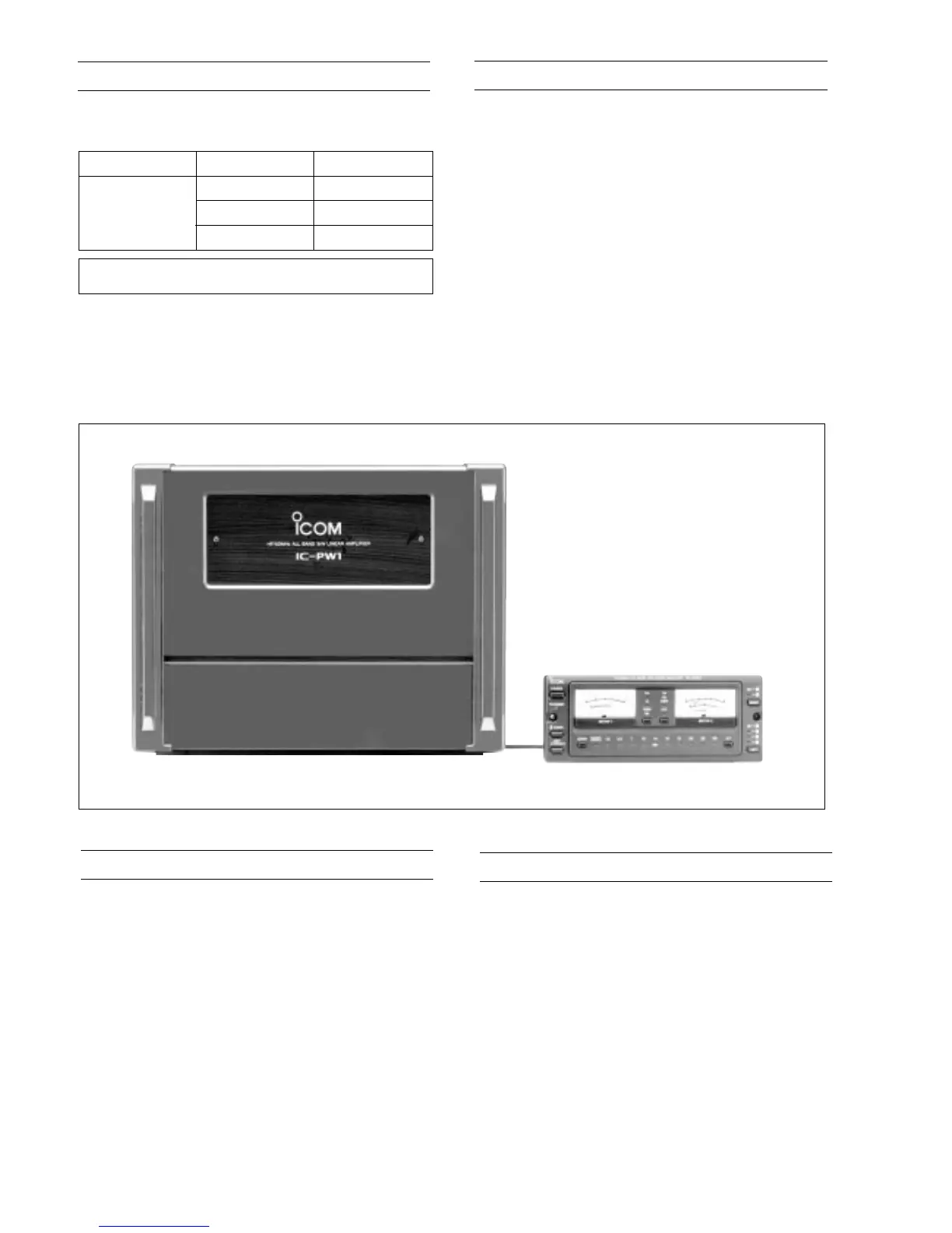
This service manual describes the latest service information for
the IC-PW1 HF/50 MHz ALL BAND LINEAR AMPLIFIER at
the time of publication.
To upgrade quality, all electrical or mechanical parts and inter-
nal circuits are subject to change without notice or obligation.
DANGER
HIGH VOLTAGE! NEVER touch the antenna con-
nector or the power supply section in the linear amplifier
while connecting the IC-PW1 to an AC outlet.
NEVER carry the linear amplifier by yourself. At least two
persons must carry the linear amplifier since it weights ap-
prox. 25 kg (55.12 lb).
NEVER expose the IC-PW1 to rain or moisture since fire
or shock hazard could occur.
NEVER touch the IC-PW1 with metal strips, wire, etc.
These materials may cause fires and electric shocks.
ORDERING PARTS
Be sure to include the following four points when ordering
replacement parts:
1. 10-digit order numbers
2. Component part number and name
3. Equipment model name and unit name
4. Quantity required
<SAMPLE ORDER>
1140003830 S.IC TC4W66F IC-PW1 MAIN UNIT 1 piece
8810003160 SET Screw 3 × 6 ZK IC-PW1 CHASSIS 6 pieces
Addresses are provided on the inside back cover for your
convenience.
REPAIR NOTES
1. Make sure a problem is internal before disassembling the
linear amplifier or the remote controller.
2. DO NOT open the linear amplifier or the remote controller
until the linear amplifier is disconnected from its power
source.
3. DO NOT force any of the variable components.
Turn them slowly and smoothly.
4. DO NOT short any circuits or electronic parts. An insu-
lated tuning tool MUST be used for all adjustments.
5. DO NOT keep power ON for a long time when the linear
amplifier is defective.
6. READ the instructions of test equipment thoroughly
before connecting equipment to the linear amplifier.
MODEL VERSION SYMBOL
Europe
Europe-1
IC-PW1
USA
EUR
EUR-1
U.S.A.
 Loading...