4 - 2
4-2 PA AND FRONT UNIT ADJUSTMENT
Idling current must be taken out the PA unit from the main body.
IDLING
CURRENT
METER
MAXIMUM
POINT
ADJUSTMENT
ADJUSTMENT ADJUSTMENT CONDITION
MEASUREMENT
VALUE
POINT
UNIT LOCATION UNIT ADJUST
1
2
3
4
1
2
• [POWER] switch : OFF
• Pre-set R9 and R10 on the PA1
board to maximum counterclock-
wise position.
• [POWER] switch : ON
• [AMP] switch : ON
• Exciter frequency : 14.1 MHz
• Mode : USB
• Apply no audio signal to the
[MICROPHONE] connector.
• Connect the lead of L6 to ground.
• Transmitting.
• Disconnect the lead of L6 from
ground.
• Connect the lead of L5 to ground.
• Transmitting.
• Disconnect the lead of L5 from
ground.
• Connect the lead of L6 to ground.
• [POWER] switch : OFF
• Connect the terminator to
[REMOTE] jack, then while push-
ing the [ANT] switch, turn power
ON.
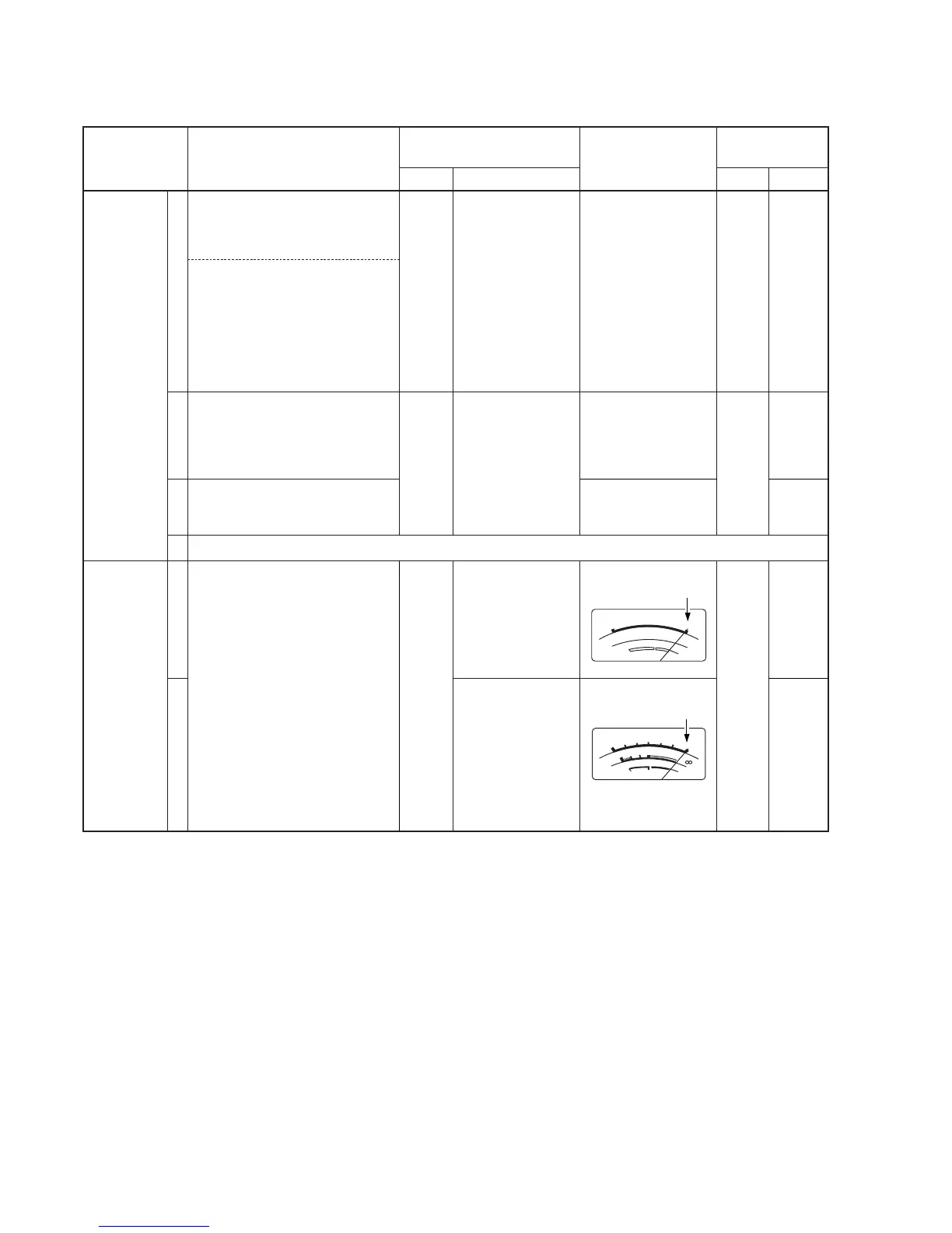
• METER-1 : [P
O] scale
• METER-2 : [VD] scale
Front
panel
Front
panel
Controller
Connect the DC
ammeter to the HV
line between PA1
board and the
power supply unit.
Connect the DC
ammeter to the HV
line between PA1
board and the
power supply unit.
[METER-1]
[METER-2]
100 mA
200 mA
200 mA
Set as below :
Set as below :
PA1
PA1
SW
R9
R10
R9
R56
R57
• Same adjustments as steps 1–4 for PA2–PA4 boards.
 Loading...