4
2
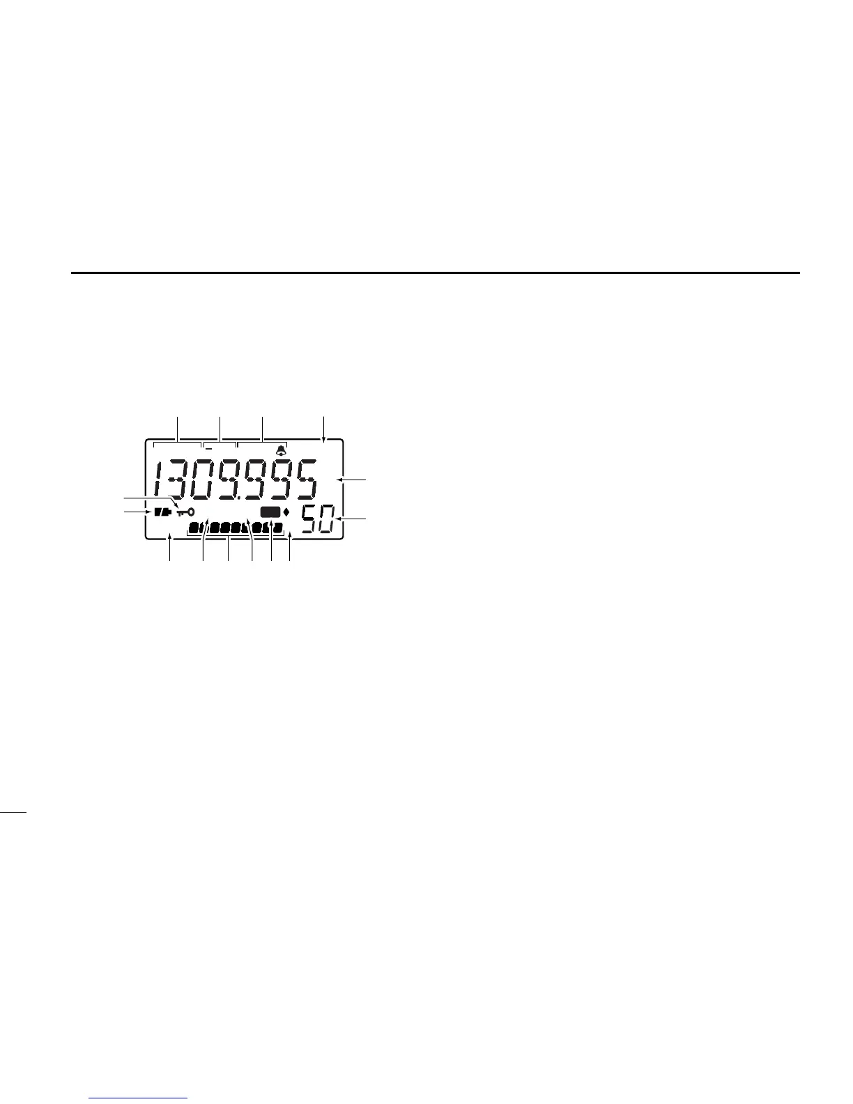
PANEL DESCRIPTION
■ Function display
q RECEIVE MODE INDICATORS (p. 11)
Show the receive mode.
•AM, FM and WFM are available.
w DUPLEX INDICATORS (p. 24)
Appear when semi-duplex operation (repeater operation)
is in use.
•“–DUP” appears when minus duplex is selected;“DUP” only, ap-
pears when plus duplex is selected.
e TONE INDICATORS (p. 22)
➥“T SQL” appears when the tone squelch function is acti-
vated and “TSQLë” appears during pocket beep oper-
ation.
➥“ë” flashes when the correct tone is received during
pocket beep operation.
r ATTENUATOR INDICATOR
Appears when the attenuator function is in use. (p. 8)
t FREQUENCY READOUT
Shows the operating frequency, set mode contents, etc.
•The smaller “75,” “50” and “25” to the right of the readout indicate
7.5, 5.0 and 2.5 kHz, respectively.
•The decimal point of the frequency flashes during scan.
y MEMORY CHANNEL READOUT
Shows the memory channel number, etc.
u MEMORY BANK INDICATORS
Indicate 8 memory banks.
•“1” – “3” indicate memory banks 1 to 3; “♦” indicates memory
bank 4; “♦1” – “♦3” indicate memory banks 5 to 7; no bank indi-
cator indicates memory bank 0.
i MEMORY MODE INDICATOR
Appears when a memory channel is selected.
 Loading...