4 - 4
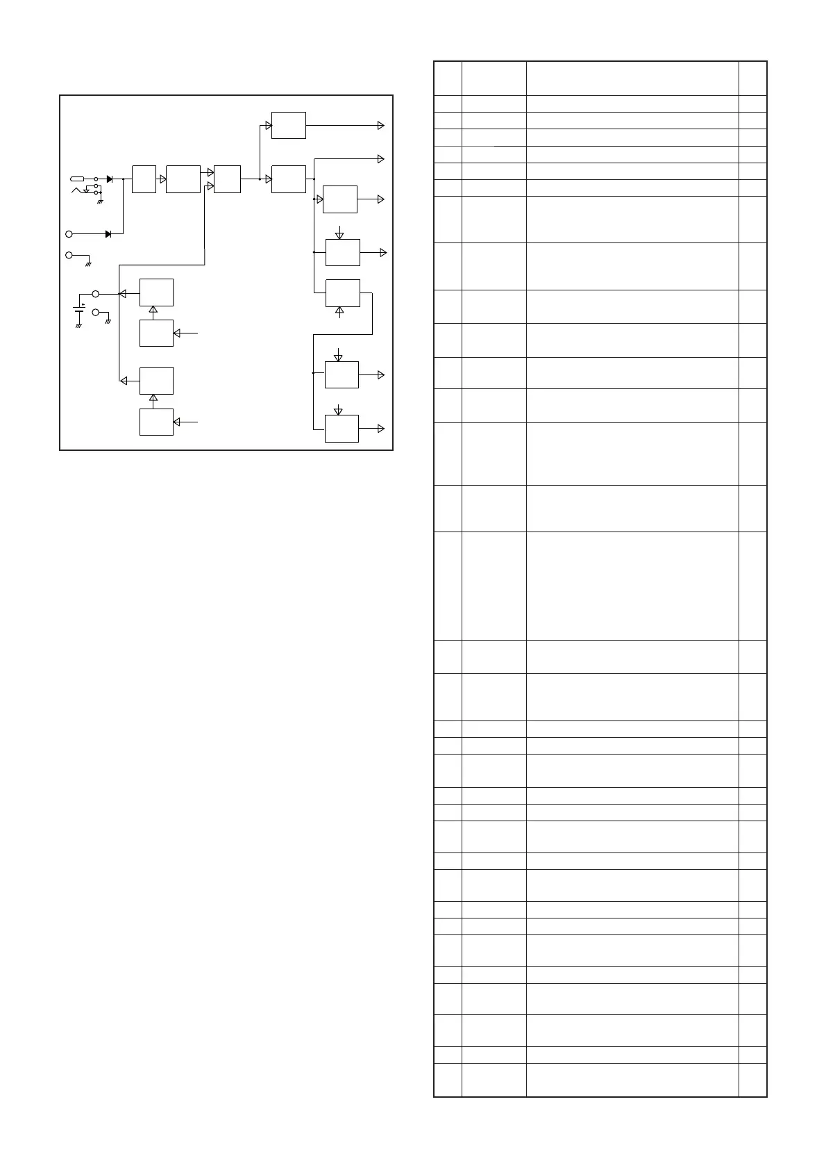
4-4 VOLTAGE BLOCK DIAGRAM
Voltage from the power supply is routed to throughout the
transceiver via regulators and switches.
4-5 CPU PORT ALLOCATION
BATTERY
PACK
J500
D508
CP3 D509
CP4
DC
SW
CHRG
CHRG
C TRL
DC-DC
CONV
RESE T
LOGI C
CTRL
+3S
CTRL
IFV
CTRL
CHGC
HV
RESET
LOGIC
3.3V
+3S
IFV
PCON
IF CON
Q500,D501
Q501,D500,D503
Q502
IC102
IC3
Q103
Q102
Q104
+3V
IC104
REG
+3.3CPU
LIMIT
D511
REG
+5V
IC455,Q512,Q513
CHRG
C TRL
Q509
CHRG
Q510,D507
CHGS
REG
+2S
IC103
+2S
+3SC
LOGIC3.3V
VCC
+3V
Pin
No.
Line
Name
Description I/O
1 IOCK Expand IC serial clock. O
2 IOSTB Expand IC strobe. O
3 IOEN Expand IC chip enable. O
4 IODATA Expand IC serial data. O
5 ESIO EEPROM serial data. I/O
6 ECK EEPROM serial clock. O
7 CHGC
Charging circuit control.
H=While regular charging.
L=While trickle charging.
O
8 TCON
Tone fi lter contol.
L= While the tone squelch function is
in use.
O
9 AMUTE
AF mute switch control.
H=AF mute.
O
15 ATT
Attenuator control.
L=The attenuator is ON.
O
16 SHIFT
1st VCO oscillation frequency range
shift.
O
17 CLS
CPU clock frequency shift.
H=Clock frequency is shifted.
O
18 DBL1
Doubler circuit (DBL1; Q31, D43,
D50) control.
L= While receiving 283–494.2 MHz
and 833–1066.7 MHz.
O
19 AF_FIL
AF filter (LOGIC UNIT: R350 and
C404) control.
H= The AF fi lter setting is ON.
O
38 AFSEL
AF filter (LOGIC UNIT: Q301/Q302)
select.
H= While receiving in the FM mode.
The AF fi lter (Q302) is selected.
L= While receiving in the WFM/
AM mode.The AF filter (Q301) is
selected.
O
41 AFON
AF power AMP control.
L=AF power AMP is activated.
O
42 LIGHT
Backlight LED control.
H= The backlight (DS2 and DS3)
lights.
O
43 VR_CLK Electric volume IC serial clock. O
44 VR_DATA Electric volume IC serial data. O
45 MODE
[MODE] input.
L= Pushed.
I
53 DUD [DIAL] input. (Data) I
54 DCK [DIAL] input. (Clock) I
98 FSET
Reference frequency adjustment
voltage.
O
99 TRAC Bar antenna tuning voltage. O
103 VSC
Demodulated AF signal input. (For
the VSC function)
I
104 K2 [UP] and [DOWN] inputs. I
105 K1 [BAND], [V/M] and [MODE] inputs. I
106 RSSI
RSSI voltage from the IF demodulator
IC (RF UNIT: IC12, pin16).
I
107 VIN Remaining battery voltage. I
108 CTONE
Tone signals (WX/MSK/TRAIN)
decoding input.
I
109 RTONE
Tone signals (CTCSS/DTCS)
decoding input.
I
110 TEMP Temperature sensing voltage. I
111 SQL
[SQL] input.
L= Pushed.
I
 Loading...