3 - 1
SECTION 3
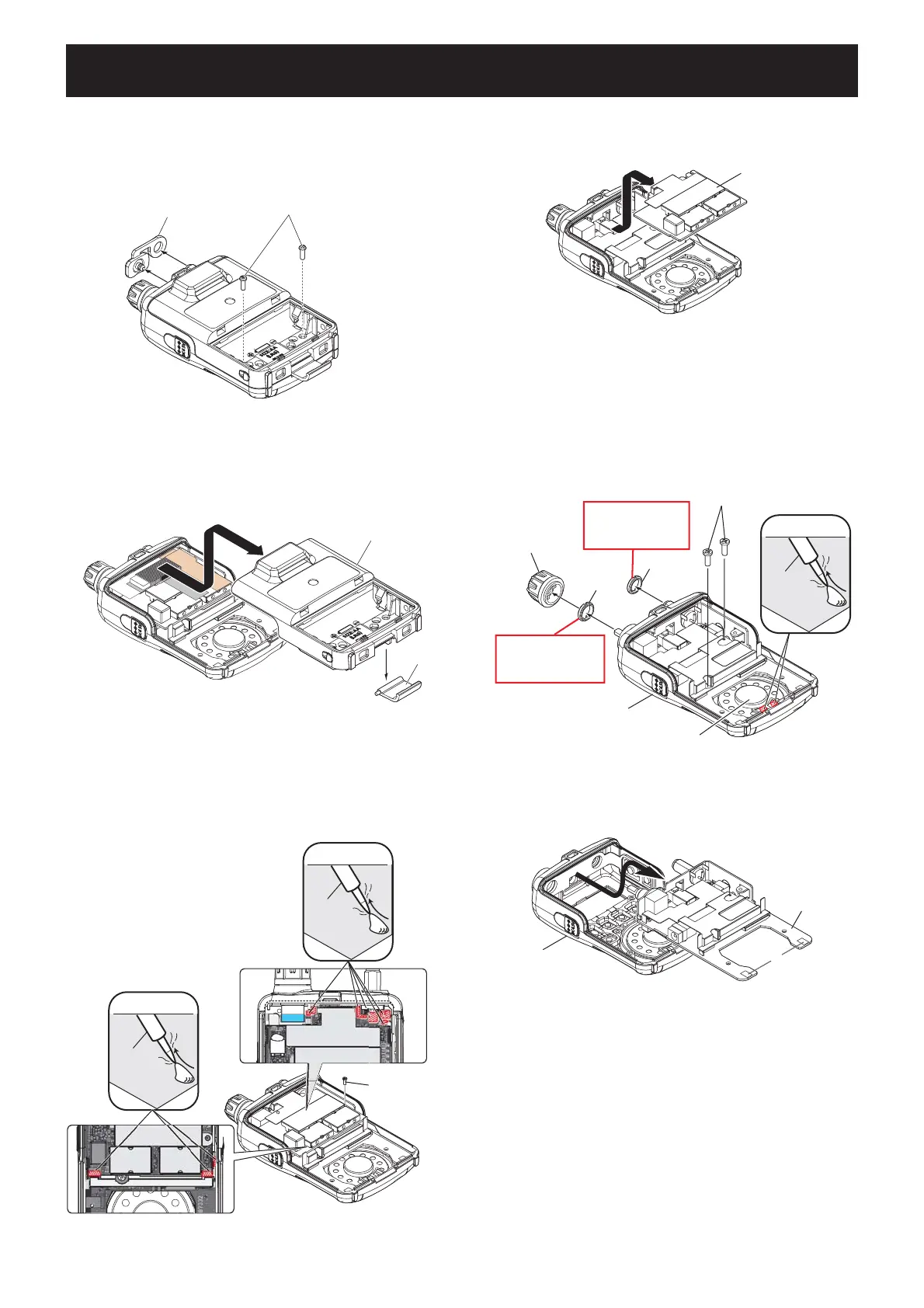
DISASSEMBLY INSTRUCTION
1. REMOVING THE REAR PANEL
1) Remove the battery cover.
2) Remove 2 screws and jack cap.
3. REMOVING THE LOGIC UNIT
1) Remove the dial knob, 2 nuts and 2 screws from the
front panel.
2) Unsolder the 2 points from the speaker.
3) Remove the rear panel in the direction of the arrow.
(NOTICE: The latch falls off when removing the rear
panel.)
SCREW×2
JACK CAP
UNSOLDER
Solder
remover
SCREW
ANT NUT
VOL NUT
DIAL KNOB
FRONT PANEL
SPEAKER
Remove with;
“ICOM Driver (L2)”
(8960000171)
“ICOM Driver (Q)”
(8960000370)
Remove with;
LOGIC UNIT
FRONT PANEL
REAR PANEL
LATCH
UNSOLDER
Solder
remover
UNSOLDER
Solder
remover
SCREW
RF UNIT
2. REMOVING THE RF UNIT
1) Remove a screw from the RF UNIT.
2) Unsolder the total of 8 points as shown below.
3) Remove the RF UNIT in the direction of the arrow.
3) Remove the LOGIC UNIT in the direction of the
arrow.
(Continued to the right above)
 Loading...