7
VOICE SCRAMBLER
2
‘‘
Preparation
D Hardware setup
The following hardware setup is required before installing the
optional UT-109/UT-110
VOICE SCRAMBLER UNIT
, as the scram-
bler unit is installed into the microphone amplifier circuit (for
transmission) and AF circuit (for reception).
D Setup instructions
q Turn the power OFF, then disconnect the power cable.
w Remove the 3 allen-socket bolts from the front panel using
with an allen wrench (2.5 mm;
1
⁄10″).
e Remove the front panel from the transceiver.
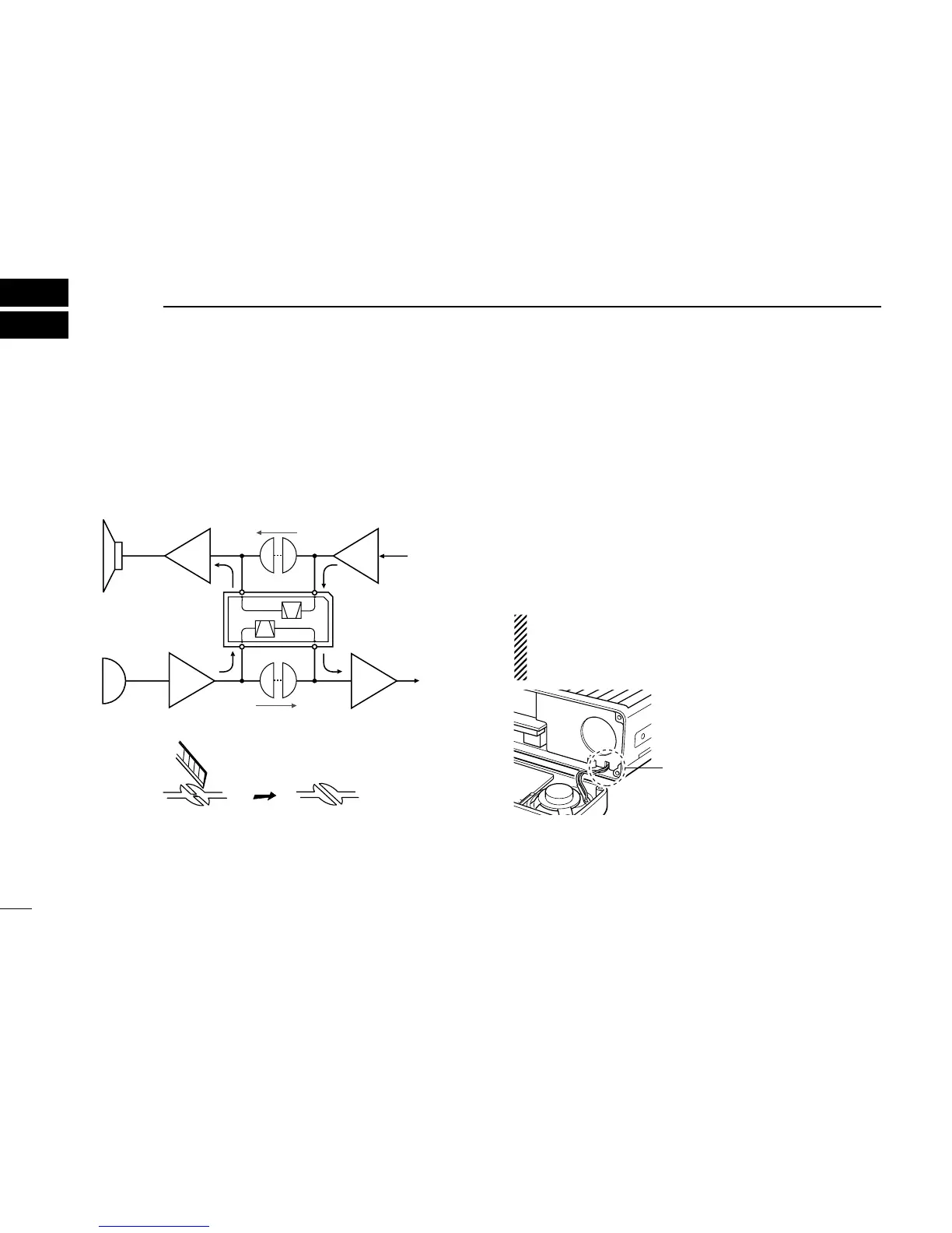
r Cut the printed circuit pattern on the PCB at point CP2 and
CP3, as described at right.
t Install the voice scrambler unit.
y Return the front panel and the allen-socket bolts to their
original position.
NOTE: When attaching the front panel to the main unit,
make sure the speaker wires are running in the groove
as illustrated below to prevent catching between front
panel and main unit.
 Loading...