5 - 1
SECTION 5
ADJUSTMENT PROCEDURE
¤ JIG CABLE
¤ POWER SUPPLY
EQUIPMENT GRADE AND RANGE EQUIPMENT GRADE AND RANGE
Power supply
Voltage range : 1–12 V DC
Current capacity : 3 A
JIG cables (See the illust shown below)
RF power meter
(50
Ω
terminated)
Measuring range : 0.1–10 W
Frequency range : 100–300 MHz
SWR : Less than 1.2 : 1
Frequency counter
Frequency range : 0.1–300 MHz
Frequency accuracy : ±0.5 ppm or better
Input level : Less than 1 mW
Modulation
Analyzer
Frequency range : 0.1–300 MHz
Measuring range : 0 to ±10 kHz
Standard signal
generator (SSG)
Frequency range : 0.1–300 MHz
Output level : –20 dBµ to 90 dBµ
(–127 to –17 dBm)
AC millivolt meter Measuring range :10 mV to 10 V Attenuator
Power attenuation : 30 dB
Capacity : More than 10 W
Voltmeter Measuring range : 1–12 V
Audio generator
(AG)
Frequency range : 300–3000 Hz
Output level : 1–500 mV
5-1 PREPARATION
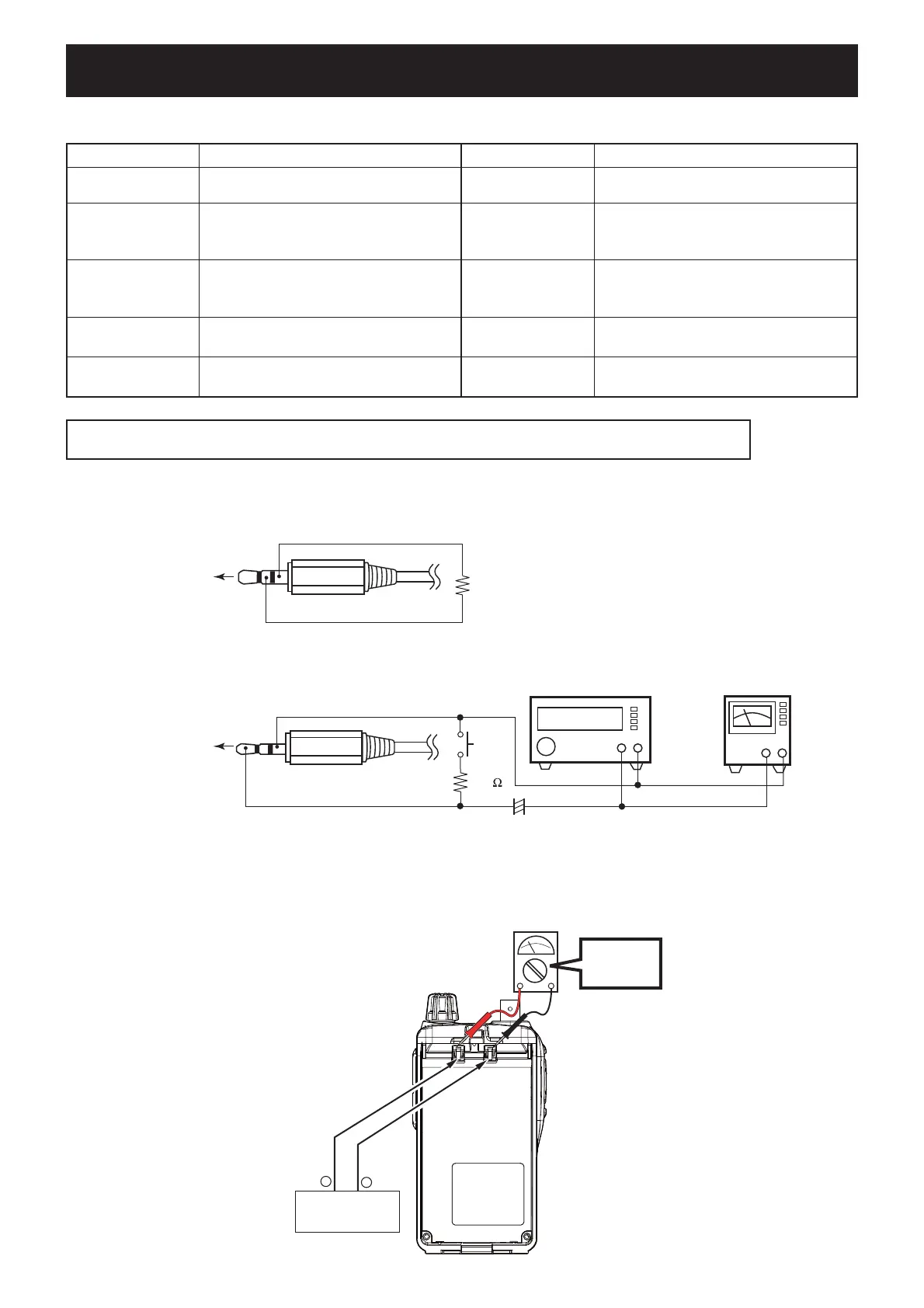
• JIG cable #1
• JIG cable #2
3-conductor 2.5 (d) mm plug
(MIC)
(GND)
33 k
+−
AC
MILLIVOLTMETER
(10 mV to 10 V)
AUDIO GENERATOR
(300–3000 Hz/1–500 mV)
+−
PTT
+
4.7 µF
3-conductor 3.5 (d) mm plug
(REMOTE)
(SP)
(GND)
82 kΩ
DC power supply
1–12 V/3 A
+
–
“7.2 V”
VOLTMETER
+
−
CAUTION!: BACK UP the originally programmed memory data in the transceiver before starting adjustment.
When the adjustment is fi nished, the memory data may be cleared.
 Loading...