EasyManua.ls Logo

IDEAL Independent + Combi C24 User Manual

IDEAL Independent + Combi C24
72 pages
To Next Page IconTo Next Page
To Previous Page IconTo Previous Page
Page #17 background image
17
INSTALLATION
Independent + Combi - Installation and Servicing
FLUE OUTLET
13
DETERMINING THE FLUE LENGTH AND FLUE PACKS REQUIRED
IMPORTANT. The boiler must be installed in a vertical position
in accordance to the installation instructions.
FLUE KITS
Telescopic Flue‘B’ Pack - contains: Flue turret, telescopic ue
incorporating a terminal and rubber wall seal.
Horizontal Flue Terminal (600mm long) ‘B’ Pack - contains:
Flue turret, non telescopic single piece ue incorporating a
terminal and rubber wall seal.
Horizontal Flue Terminal (1000mm long) ‘B’ Pack - Flue turret,
telescopic ue incorporating a terminal, rubber wall seal and
instructions.
Note. If ‘B’ packs are used on their own (either 1 piece or
telescopic), then they can be tted horizontally as the ue
inside is designed to slope 1.5 degrees.
Flue Kit 203129 - D Pack Flue Extension 100mm DIA 1000mm long
Flue Kit 211037 - D Pack Flue Extension 100mm DIA 500mm long
Flue Kit 211038 - D Pack Flue Extension 100mm Dia 2000mm long
Flue Kit 211039 - Roof Flue Kit with Vertical Connector
When extension ‘D’ Packs are used the ue duct must incline
1.5 degrees away from the appliance, to allow the condensate
to drain back to the boiler and out of the condensate drain. It is
recommended that a support bracket is tted on every 1 metre of
pipe work used and the bracket is located as close to the collar
as possible. The bracketing must ensure a 1.5 degree fall back
to the appliance.
Optional Flue Finishing Kit - UIN 155988 & Concentric Flue
Screw Retaining Kit (Optional Kit of mechanical xing of ue
joints)
Only use water as a lubricant during assembly.
The ‘B’ pack terminal is classed as part of the maximum ue
length.
These ue systems incorporates a removable ue outlet
nose that utilises a push t location system. This enables the
installation of deector, high level or balcony ue kits without
the removal of the whole ‘B’ pack terminal. The appliance must
not be operated without the desired outlet nose correctly tted
in place, ensuring the side location dimples are in line with the
mounting face allowing the correct sealing of the components.
It is IMPORTANT that all attachments are tted in accordance
to the installation instructions provided with them.
The TURRET supplied in the ‘B’ Pack has an upper combustion
sample point with a screw cap seal and a lower air sample point
with an air stopper seal. Ensure all caps & seals are in place.
‘D’ Pack - contains: 1 metre length of ue pipe (Functional length 950mm), 1 support bracket and instructions.
Additional Termination Kits available for use with these ‘B’ packs.
Flue Deector Kit The resistance is the equivalent of 1 metre of ue pipe and therefore must be deducted from
any maximum ue length
High Level Flue Outlet Kit
The maximum permissible concentric ue length when using a standard (500mm) kit is 4.5 metres
Balcony Flue Outlet Kit The maximum permissible concentric ue length when using this kit is dependant on the length
of the balcony ue outlet run which combined with the concentric run must not exceed the
maximum ue length requirement of the appliance it is to be tted to
Soft Kit This kit enables tment of an external ue below softs.
Total Maximum Permissible Horizontal Concentric Flue Length combining both ‘B’ Packs and ‘D’ Packs
(Measured from centreline of the turret to the outside of the wall terminal)
24 kW appliances Total Maximum: 9 metres - minus any ue kit options or bends
30 kW Appliances Total Maximum: 8 metres - minus any ue kit options or bends
35 kW Appliances Total Maximum: 6 metres - minus any ue kit options or bends
Total Maximum Permissible Vertical Flue Length combining both Roof Terminal and ‘D’ Packs
24, 30 & 35kW Appliances Total Maximum: 7.5 Metres - minus any bends
90º Elbow Kit 60/100 - (Equivalent ue length resistance = 1M)
45º Elbow Kit 60/100 - (Equivalent ue length resistance = 0.6M)
Minimum Horizontal Flue Lengths (Centre line of turret to outside of wall terminal)
Telescopic Flue ‘B’ Pack = 400mm
Horizontal Flue terminal (600mm long) ‘B’ Pack = 285mm
Wall Thickness Std Metric Brick 102.5mm wide
‘B’ Pack Flue Type Minimum permissible Wall Thickness Maximum permissible Wall Thickness
Rear Flue Rear Flue + Std-Off Side Flue Rear Flue Rear Flue + Std-Off Side Flue
Horizontal Flue Terminal
(600mm long) B Pack
116 102.5 102.5 501 456 456
Telescopic Flue B Pack 231 186 186 429 384 384
Horizontal Flue Terminal
(1000mm long) B Pack
546 501 501 761 716 716
Horizontal Flue Terminal
(1000mm long) B Pack cut 75mm
471 426 426 686 641 641
For Flue lengths between 658 & 708 use a Horizontal Flue Terminal (1000mm long) B Pack, cut 75mm off the end of the
terminalsectionofthetelescopicueonly.

Table of Contents

Question and Answer IconNeed help?

Do you have a question about the IDEAL Independent + Combi C24 and is the answer not in the manual?

IDEAL Independent + Combi C24 Specifications

General IconGeneral
Boiler TypeCombi
Output24 kW
Fuel TypeGas
Efficiency (%)94%
Dimensions (H x W x D)700 x 395 x 278 mm
Weight28.6 kg
ErP RatingA
Warranty2 years
MountingWall Mounted
Hot Water Flow Rate9.8 l/min
FuelNatural Gas
EfficiencyA Rated

Summary

INSTALLATION AND SERVICING

Document Amendments

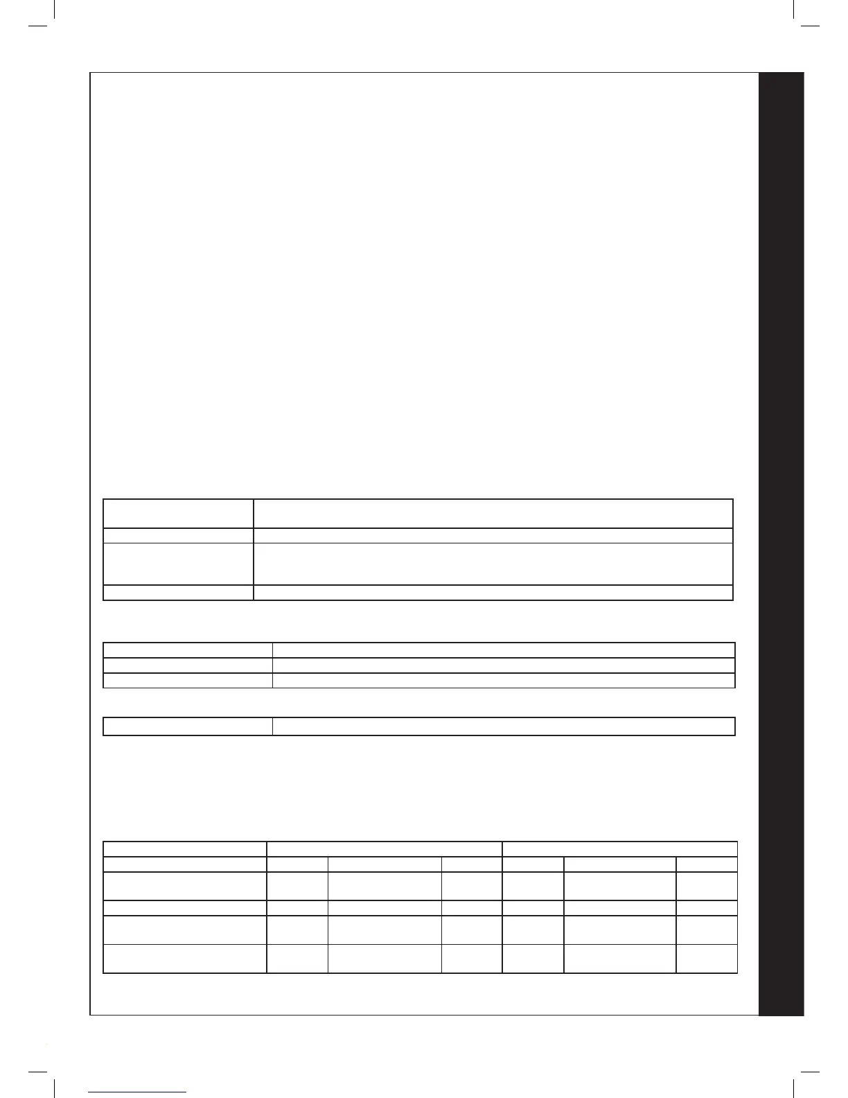
Details of document amendments are available on page 3.

NOTES FOR THE INSTALLER

DOCUMENT AMENDMENTS

Details relevant installation changes implemented in this book from Mod Level.

GENERAL

Key to symbols

Provides a key to understanding the symbols used throughout the manual.

GENERAL

BENCHMARK COMMISSIONING CHECKLIST DETAILS

Details required for the Benchmark Commissioning Checklist.

INTRODUCTION

SAFE HANDLING

Guidance on safe techniques and precautions for moving and handling the boiler.

SAFETY

LOCATION OF BOILER

Specifies regulations and considerations for selecting the boiler's installation site.

GAS SUPPLY

FLUE INSTALLATION

Recommendations and guidance for correctly installing the boiler's flue system.

AIR SUPPLY

CONDENSATE DRAIN

Instructions and requirements for connecting and managing the boiler's condensate drain.

BOILER DIMENSIONS, SERVICES & CLEARANCES

Front clearance

Specifies minimum front clearance requirements for the boiler installation.

SYSTEM REQUIREMENTS - Central Heating

DOMESTIC HOT WATER

Requirements and considerations for domestic hot water services and connections.

SYSTEM BALANCING

WATER TREATMENT

Recommendations for water treatment in central heating and domestic hot water systems.

INSTALLATION

BOILER ASSEMBLY - Exploded View

An exploded view illustrating the various components of the boiler assembly.

UNPACKING

HARDWARE PACK CONTENTS

Details the contents of the hardware packs provided with the boiler.

UNPACKING CONT'D

FRONT PANEL REMOVAL

Step-by-step instructions for safely removing the boiler's front panel.

WALL MOUNTING TEMPLATE

PREPARING THE WALL

Instructions for preparing the wall surface and drilling holes for boiler mounting.

DETERMINING THE FLUE LENGTH AND FLUE PACKS REQUIRED

Additional Termination Kits

Lists available additional kits for flue termination to suit various installation scenarios.

CUTTING & SETTING THE FLUE LENGTH

CUTTING HORIZONTAL FLUE TERMINAL (600MM LONG) B PACK

Instructions for cutting and preparing the horizontal flue terminal for installation.

INSTALLING THE FLUE

FITTING THE TURRET

Guidance on fitting the flue turret and ensuring proper sealing and connection.

FITTING THE OPTIONAL ROOF FLUE KIT (Flat or Pitched)

ROOF FLUE KIT CONTENTS / OPTIONS

Details the components and options available for installing a roof flue kit.

FLUE TERMINAL POSITION

Table for Terminal Positions

Specifies minimum dimensions for flue terminal positions relative to building features.

ASSEMBLING THE ROOF FLUE KIT

Extension Duct

Instructions for fitting extension ducts to achieve the required flue length.

CONDENSATE DRAIN

Internal Drain Connections

Describes methods for routing condensate drainage to internal discharge points.

CONDENSATE DRAIN - CONT'D

Figure 3 - Connection of a Condensate Pump

Illustrates the typical method for connecting a condensate pump.

CONNECTIONS & FILLING

WATER CONNECTIONS CH

Instructions for connecting the Central Heating flow and return valves.

ELECTRICAL CONNECTIONS

INTERNAL WIRING

Details on connecting the internal wiring of the boiler to the mains supply.

WIRING DIAGRAM

KEY

Provides a key for understanding the colour coding used in the wiring diagram.

COMMISSIONING AND TESTING

GENERAL

General notes and checks to be performed after installation and before operation.

INITIAL LIGHTING

THE DISPLAY

Explains the boiler status display codes and their meanings during normal operation.

GENERAL CHECKS

WATER TEMPERATURES

Information on selecting and adjusting central heating and domestic hot water temperatures.

RESTART PROCEDURE

HANDING OVER

Steps for the installer to hand over the boiler and system to the householder.

SERVICING SCHEDULE

COMPETENCE TO CARRY OUT THE CHECK OF COMBUSTION PERFORMANCE

Specifies requirements for personnel performing combustion analysis.

BOILER FRONT PANEL REMOVAL / REPLACEMENT

FAN AND VENTURI ASSEMBLY REMOVAL AND CLEANING

Instructions for removing, cleaning, and refitting the fan and venturi assembly.

BURNER REMOVAL AND CLEANING

CLEANING THE CONDENSATE TRAP/SIPHON

Procedure for cleaning the boiler's condensate trap or siphon.

CLEANING THE HEAT EXCHANGER

REASSEMBLY

Detailed steps for reassembling the boiler components after servicing.

REPLACEMENT OF COMPONENTS

FAN REPLACEMENT

Step-by-step guide for replacing the boiler's fan assembly.

BURNER INJECTOR REPLACEMENT

BURNER REPLACEMENT

Instructions for removing and replacing the boiler's burner assembly.

RETURN THERMISTOR RENEWAL

IGNITION ELECTRODE REPLACEMENT

Procedure for replacing the ignition electrode, including gap setting.

FLAME DETECTION ELECTRODE REPLACEMENT

SPARK GENERATOR REPLACEMENT

Guide to replacing the spark generator, ensuring correct connections.

GAS CONTROL VALVE REPLACEMENT

DIVERTER VALVE ACTUATOR REPLACEMENT

Instructions for replacing the diverter valve actuator, including motor removal and fitting.

CONDENSATE TRAP/SIPHON REPLACEMENT

MAIN PCB REPLACEMENT

Detailed steps for replacing the main Printed Circuit Board (PCB) and its associated components.

USER CONTROL PCB REPLACEMENT

REPLACING THE MECHANICAL TIMER

Instructions for replacing the mechanical 24-hour timer unit.

DHW FLOW TURBINE SENSOR REPLACEMENT

DRAINING THE BOILER

Procedures for draining both the central heating and domestic hot water circuits.

SAFETY RELIEF VALVE RENEWAL

PUMP AUTOMATIC AIR VENT REPLACEMENT

Guide for replacing the automatic air vent located in the pump body.

DIVERTER VALVE BODY ASSEMBLY REPLACEMENT

DHW PLATE HEAT EXCHANGER REPLACEMENT

Instructions for removing and replacing the domestic hot water plate heat exchanger.

CH WATER PRESSURE SWITCH REPLACEMENT

DHW FILTER & DHW FLOW REGULATOR CLEANING / REPLACEMENT

Procedure for cleaning or replacing the DHW filter and flow regulator.

HEAT ENGINE RENEWAL

EXPANSION VESSEL RECHARGING & REPLACEMENT

BOILER SEALING PANEL SEAL REPLACEMENT

Instructions for replacing the boiler's sealing panel and ensuring an airtight seal.

FAULT FINDING

ALTERNATING 'L' AND '1' - FLOW TEMPERATURE OVERHEAT LOCKOUT

Troubleshooting steps for flow temperature overheat lockout errors.

ALTERNATING 'L' AND '5' - 5 RESTARTS WITHIN 15 MINS

ALTERNATING 'F' AND '1' - LOW WATER PRESSURE

Troubleshooting steps for low water pressure faults and error codes.

ALTERNATING 'F' AND '2' - FLAME LOSS

ALTERNATING 'F' AND '3' - FAN FAULT

Troubleshooting steps for flame loss and fan fault error codes.

ALTERNATING 'F' AND '5' - RETURN THERMISTOR FAULT

ALTERNATING 'F' AND '6' - OUTSIDE SENSOR FAULT

Troubleshooting steps for return thermistor and outside sensor faults.

ALTERNATING 'F' AND '9' - PCB FAULT

ALTERNATING 'c' AND '2' - BCC FAULT (BOILER CHIP CARD)

Troubleshooting steps for PCB and Boiler Chip Card (BCC) faults.

ALTERNATING 'C' AND '0' - LOW MAINS VOLTAGE

NO CH OPERATION BUT HW WORKS OK

Troubleshooting steps when central heating is not operating but hot water is functional.

NO HW BUT CH ON

NO DISPLAY

Troubleshooting steps for issues related to no hot water but central heating on, and no display.

SPARE PARTS

Code Of Practice

Standards of Work

Outlines the expected standards of competence and practice for installers.

Benchmark Commissioning and Servicing Section

GAS BOILER SYSTEM COMMISSIONING CHECKLIST

SERVICE RECORD

Service Provider

Information for service providers on completing service records and using spare parts.

FLOWCHART FOR CO LEVEL AND COMBUSTION RATIO CHECK ON COMMISSIONING A CONDENSING BOILER

Important Preliminary Information on Checks

Key preliminary checks and information before performing CO level and combustion ratio checks.

Technical Training

USERS

INDEPENDENT+ COMBI C24 C30 C35

Identifies the specific boiler model covered by the user guide.

INTRODUCTION

SAFETY

Details current Gas Safety regulations and essential safety precautions for boiler installation.

BOILER OPERATION

TO START THE BOILER

Step-by-step guide for starting the boiler and understanding its initial operation.

EFFICIENT HEATING SYSTEM OPERATION

SYSTEM WATER PRESSURE

Information on monitoring and maintaining the central heating system's water pressure.

GENERAL INFORMATION

MINIMUM CLEARANCES

Specifies the minimum clearances required around the boiler for servicing and operation.

POINTS FOR THE BOILER USER

TROUBLESHOOTING

A guide to help users identify and resolve common issues with the boiler's operation.

NORMAL OPERATION DISPLAY CODES

FAULT CODES

Related product manuals