18
Installation and Servicing
SECTION 2 - INSTALLATION
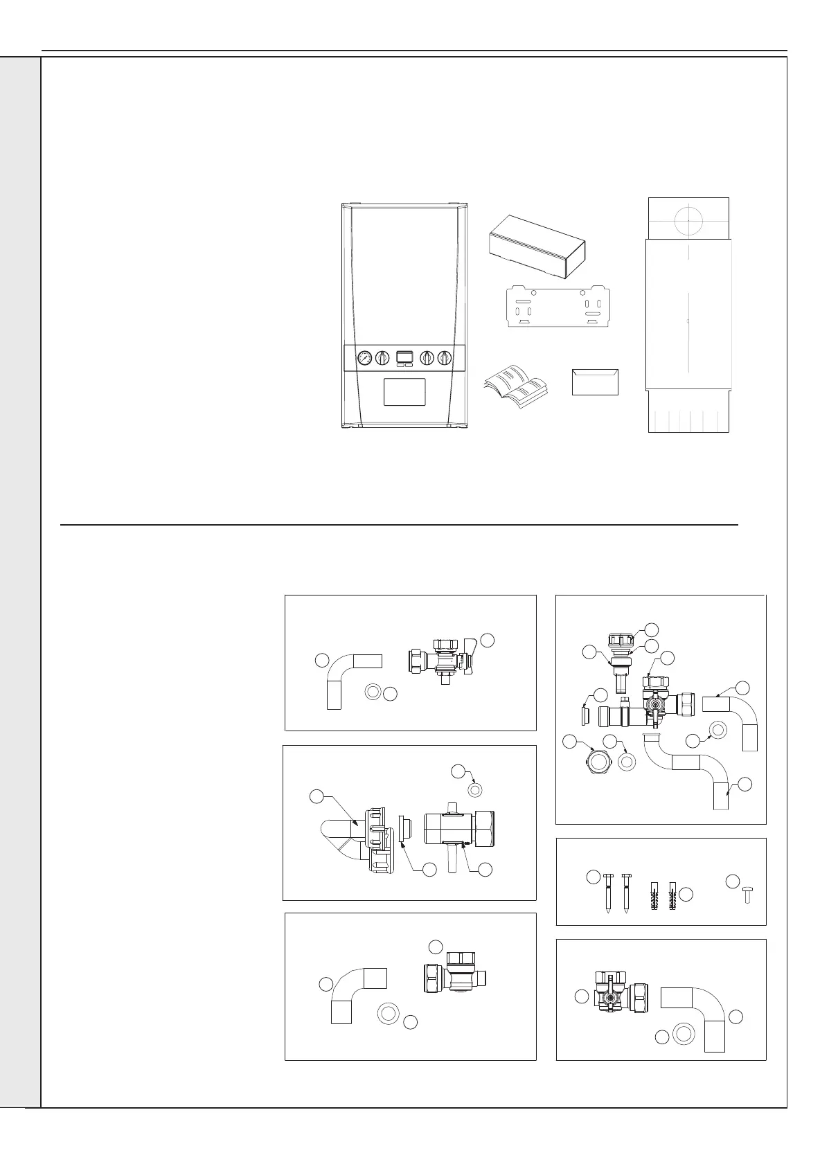
2.2 UNPACKING
The boiler is supplied fully assembled in Pack A. A telescopic or non-telescopic ue assembly for rear or side ue outlet in Pack
B is supplied as a separate order.
Unpack and check the contents.
Pack A Contents
A Boiler
B Hardware Pack Box
C Wall Mounting Plate
D These Installation/Users Instructions
E Wall Mounting Template
F Boiler Guarantee & Registration Pack
HARDWARE PACK CONTENTS
Gas Valve Pack
1. Pipe - Gas Inlet
2. Washer - Gas (blue)
3. Gas Cock
Filling Loop Pack
1. 3/8" Top Hat Washer
2. Valve Filling Loop
3. Pipe Filling Loop
4. Washer Fibre 3/8”
Return Valve Pack
1. Pipe CH Return
2. Washer CH
3. Valve Return
DHW Pack
1. 1/2" Top Hat Washer (x2)
2. Cap Female
3. Plug Male and Clip
4. Nut G1/2 16 Brass (Flat)
5. Washer 18.5 x 11 x 11.8 (x2)
6. Pipe DHW Outlet
7. Pipe DHW Inlet
8. Valve DHW Inlet
Accessory Pack
1. Screw (x2)
2. Wallplug (x2)
3. Turret Clamp Screw (spare)
Flow Valve Pack
1. Pipe CH Flow
2. Washer CH
3. Valve Flow
Gas Valve Pack DHW Pack
Accessory Pack
Flow Valve Pack
Return Valve Pack
Filling Loop
1
1
1
1
2
3
3
2
2
2
3
3
2
8
3
3
1 2
1
7
5
6
4
1
5
4
continued . . . . .
INSTALLATION
 Loading...