54
Installation and Servicing
SECTION 3 - SERVICING
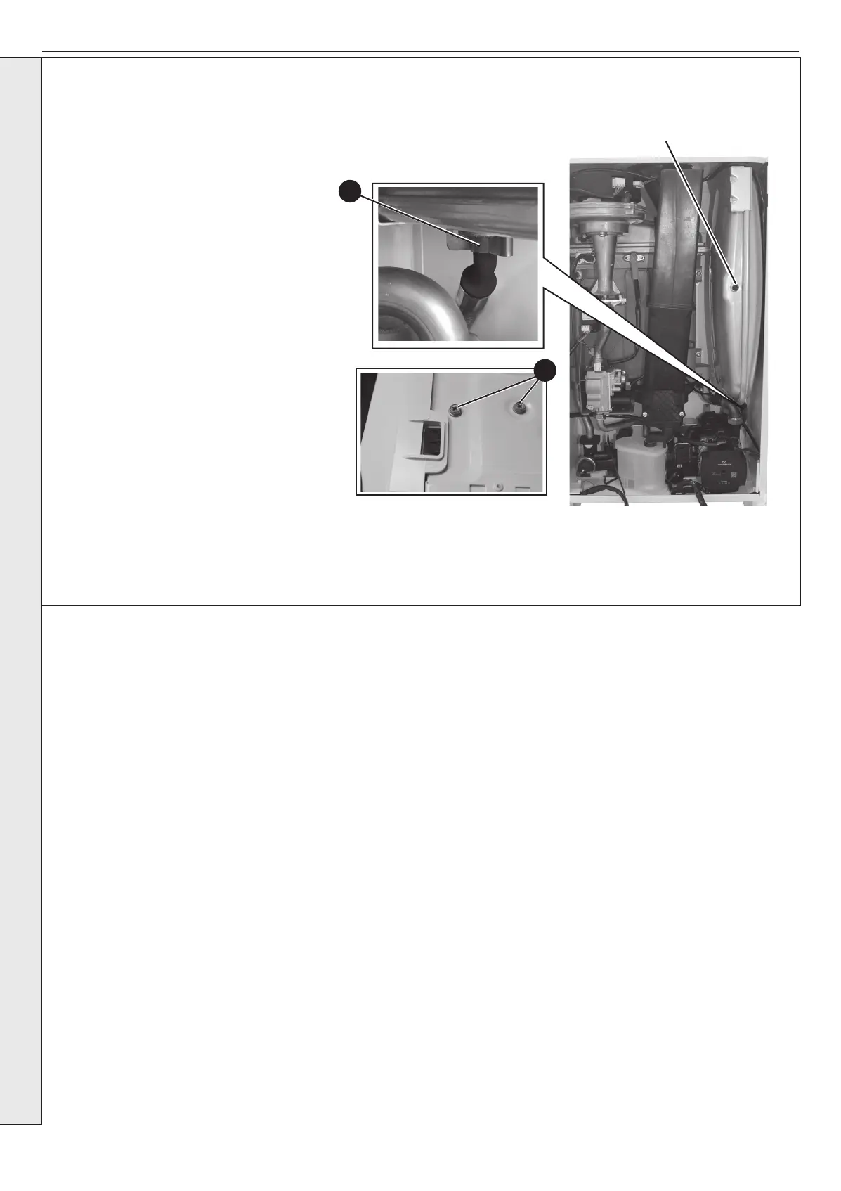
3.32 EXPANSION VESSEL RECHARGING & REPLACEMENT
8
9
RECHARGING
1. Refer to Section 3.8.
2. Remove the charge point cover.
3. Recharge the tank pressure to 0.75 bar.
4. Re-assemble in reverse order.
5. Check that the boiler operates in both DHW &
CH modes.
REPLACEMENT
6. Refer to Section 3.8.
7.
Drain the boiler CH circuit. Refer to Section 3.21.
8. Remove the retaining clip on the vessel water
connection pipe and remove the pipe.
9. Support the expansion vessel and unscrew the
2 screws from the securing bracket, located
on the top of the boiler, and remove. (Note the
position of the bracket on the vessel)
10. Remove the expansion vessel.
11. Fit the new expansion vessel.
12. Reassemble in reverse order ensuring the seal
is in place.
13. Rell the boiler and check for leaks. Refer to
Section 2.18.
14. Check tht the boiler operates in both DHW &
CH modes.
Recharge
Point
SERVICING
 Loading...