51
Installation and Servicing
SECTION 3 - SERVICING
3.26 DIVERTER VALVE BODY ASSEMBLY REPLACEMENT
1. Refer to Section 3.8.
2. Drain the boiler. Refer to Section 3.21.
3. Remove condensate trap/siphon. Refer to Section 3.18.
4. Remove the diverter valve actuator. Refer to Section 3.17.
5. Remove the 2 allen screws securing the plate heat exchanger
to the composite housings.
6. Manoeuvre the plate heat exchanger out of the top LH or
centre of the controls area. Be aware of any water spillage.
7. Fit the new plate heat exchanger, using the new o-rings
supplied.
Note. Ensure that the depressions are on the bottom prior to
tting.
8. Reassemble in reverse order.
9. Rell the boiler. Refer to Section 2.16.
10. Check that the boiler operates in both DHW & CH modes.
3.27 DHW PLATE HEAT EXCH. REPLACEMENT
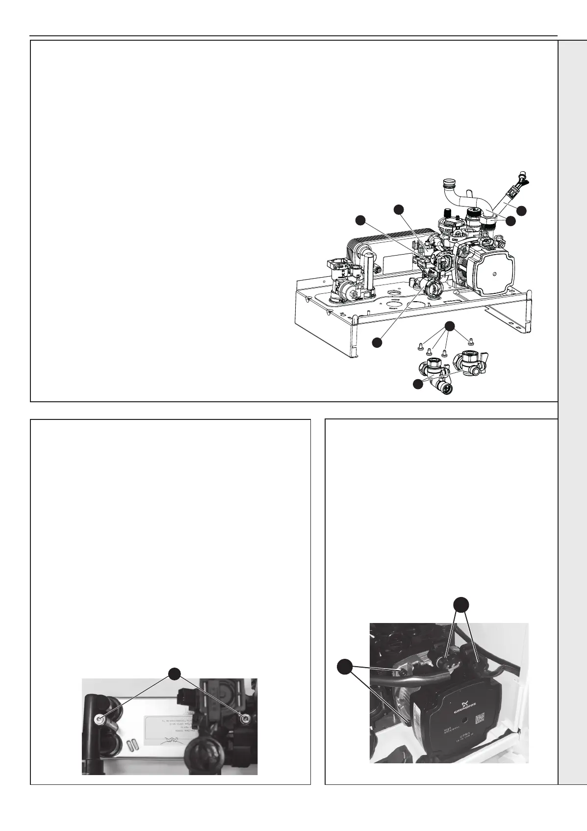
3.28 PUMP HEAD REPLACEMENT
1. Refer to Section 3.8.
2. Drain the boiler. Refer to Section 3.21.
3. Disconnect the two electrical leads from the pump.
4. Remove the 4 allen screws retaining the pump head.
5. Remove the pump head.
6. Fit the new pump head.
7. Reassemble in reverse order.
8. Rell the boiler. Refer to Section 2.16.
9. Check that the boiler operates in both DHW & CH
modes.
3
4
5
11
12
14
13
16
18
17
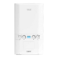
To remove the valve body assembly:
1. Refer to Section 3.8.
2. Drain the boiler. Refer to Section 3.21.
3. Remove the condensate trap/siphon. Refer to Section 3.18.
4. Remove the electrical plug. Refer to Section 3.17.
5. Place a at bladed screwdriver in the diverter
valve motor body slot provided and ease out the
motor. Refer to Section 3.17.
6. Remove the return thermistor electrical connection. Refer to
Section 3.12.
7. Remove the pump electrical connections. Refer to Section
3.28 no. 3.
8. Remove DHW Turbine electrical connection. Refer to
Section 3.20 no. 3.
9. Remove the DHW plate heat exchanger (note orientation).
Refer to Section 3.27.
10. Undo the safety valve pipe compression tting. See No.5
Section 3.23.
11. Loosen the nut above pump and rotate the pipe.
12. If required remove expansion vessel connection hose.
Refer to Section 3.32.
13. Remove the DHW inlet and CH return connection situated
beneath the boiler.
14. Remove the four torx head screws xing the return
manifold to the boiler sheet steel base.
15. Lift the manifold assembly and remove from boiler.
16. Twist and remove the DHW manifold.
17. Remove the two diverter valve body xing screws and
withdraw the diverter valve body assembly.
18. Fit the new diverter valve body assembly and replace the
two xing screws.
19. Ret the DHW manifold, t the assembly back to the boiler
and reassemble in reverse order.
20. Rell the boiler. Check that the boiler operates in both DHW
& CH modes.
SERVICING
 Loading...