33
Installation and Servicing
SECTION 2 - INSTALLATION
2.20 REPLACING PRE-FITTED MAINS CABLE
If it is necessary to use an alternative mains cable to the one pre-tted then use
the following guide.
Replacement wiring should comply with notes in Section 2.18 and be caried out
by a qualied person to avoid a hazard.
1. Isolate the mains supply to the boiler.
2. Remove the front panel. Refer to Section 3.2.
3.
Swing the control box down into the service position, unclip and swing back the
installer wiring cover to latch into the retaining clips. Refer to Section 3.8.
4. Unplug the mains connector and release the cable from strain relief.
5. Unscrew the L N & E connections & remove wires from connector.
6. Remove the mains cable by pulling back through the grommet .
7. Route the replacement through the grommet and re-t in reverse order.
8. Close the installer wiring cover ensuring that it is located correctly and that the
cable is retained into the strain relief as shown.
9. Swing the control box back up into the operating position and re-t the front
panel ensuring a good seal is made.
NOTE. When making the mains electrical connections to the boiler it is important
that the wires are prepared in such a way that the earth conductor is longer than
the current carrying conductors, such that if the cord anchorage should slip, the
current carrying conductors become taut before the earthing conductor.
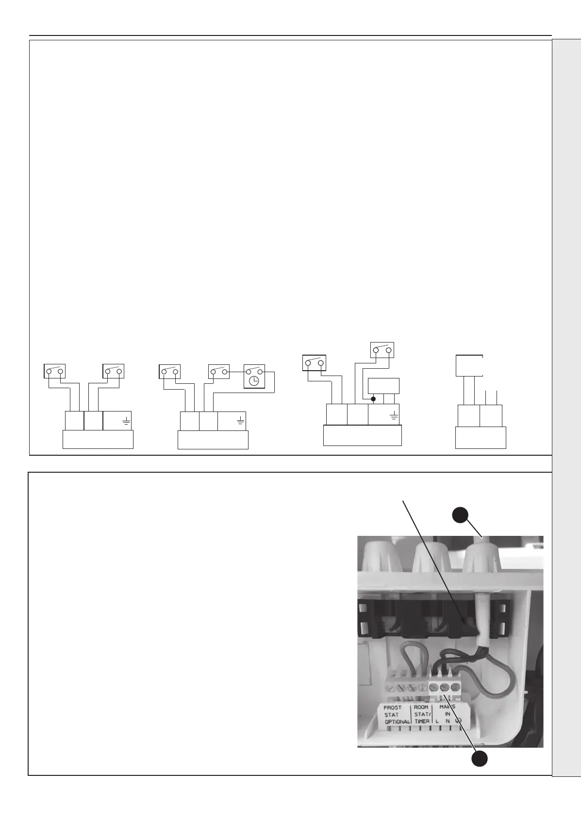
2.19 EXTERNAL WIRING
DIAGRAM A:
DIAGRAM B:
Room Stat with External Timer
Programmable Room Stat or
Room Stat with Internal Timer
Optional Room Stat or
Frost Programmable
Stat Room Stat
F r o s t
Room
Stat
Stat/
L N
(Optional)
Timer
(Optional)
Timer
DIAGRAM C:
Use of General Live for Room Stat
Optional
Room Stat
Frost
Stat
Mains In
F r o s t
Room
Stat
Stat/
L N
(Optional)
Timer
DIAGRAM A: DIAGRAM B:
Room Stat with External Timer
Programmable Room Stat or
Room Stat with Internal Timer
Optional Room Stat or
Optional
Frost Programmable
Frost
Stat Room Stat
Stat
Room Stat Timer
F r o s t
Room
F r o s t
Room
Stat
Stat/
L N
Stat
Stat/
L N
(Optional)
Timer
(Optional)
Timer
DIAGRAM C:
Use of General Live for Room Stat
Optional
Room Stat
Frost
Stat
Mains In
F r o s t
Room
Stat
Stat/
L N
(Optional)
Timer
DIAGRAM B:
Room Stat with External Timer
Programmable Room Stat or
Room Stat with Internal Timer
Optional Room Stat or
Optional
Frost
Stat
Room Stat Timer
F r o s t
Room
Stat
Stat/
L N
(Optional)
Timer
DIAGRAM C:
Use of General Live for Room Stat
Optional
Room Stat
Frost
Stat
Mains In
F r o s t
Room
Stat
Stat/
L N
(Optional)
Timer
DIAGRAM D:
OpenTherm Device
DO NOT CONNECT 230V TO THESE
TERMINALS OR THE BOILER ELECTRONICS
WILL BE DAMAGED
Outside
Sensor
Open
Therm
OpenTherm Device
E.G. Honeywell OT
Bridge R8810
Strain Relief
External Controls – 230V 50Hz
Wiring a 230V 50Hz Room Thermostat,
Diagram A (with optional timer, Diagram
B)
1. Remove the link wire from the room
stat/timer plug.
2. Connect the external cable from
the room stat/timer across these
two connections, if a general live
connection is used for the room stat
or timer then connect this to the
fused spur, on the load side (see
Diagram C)
3. If the room thermostat has
compensation and requires a neutral
connection, make this connection to
the fused spur, on the load side.
External Controls – Extra Low Voltage
Wiring OpenTherm Room Control
or other OpenTherm Master Device,
Diagram D.
1. Remove the timer link plug inside
the timer option cover, located on
the front of the control box
2. Unclip the timer link socket from the
aperture on the rear of the control box,
locate the plug on the same harness
branch and connect these together.
3. Using the rubber bung located
adjacent to these connections, insert
it into the open aperture.
4. Locate the OpenTherm connection on
the right hand side of the boiler installer
connections area and connect the 2
core cable from the OpenTherm device.
Frost Protection
If parts of the pipework run outside the
house or if the boiler will be left off for more
than a day or so then a frost thermostat
should be wired into the system.
This is usually done at the programmer, in
which case the programmer selector switches
are set to OFF and all the other controls
MUST be left in the running position.
The frost thermostat should be sited in a
cold place but where it can sense heat
from the system.
Wiring a system frost thermostat, see
digarams A, B and C. Wire the frost
thermostat across the two connections
as shown.
Note. If the boiler is installed in a garage it
may be necessary to t a pipe thermostat,
preferably on the return pipework.
INSTALLATION
6
4
 Loading...