59
FAULT FINDING FAULT FINDING FAULT FINDING FAULT FINDING FAULT FINDING
Installation and Servicing
SECTION 4 - FAULT FINDING
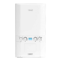
4.10 ‘F6’ - OUTSIDE SENSOR FAULT
Disconnect the wires to the outside sensor.
Check the resistance using a suitable multimeter
connected across the Outside Sensor’s terminal pins.
At 0
o
C expect 31,000 - 35,000 Ohms
At 15
o
C expect 15,000 - 16,500 Ohms
At 30
o
C expect 7,700 - 8,500 Ohms
Is the Outside Sensor value correct?
YES
Is the wiring securely connected between the
incoming terminal block boiler connection of the
Outside Sensor and the PCB?
Replace PCB
Fit a new Outside Sensor
NO
Securely connect the wiring at the
Terminal Block and the PCB
Is the wiring securely connected at both the boiler and
Outside Sensor?
YES
NO
Securely connect the wiring at both the
boiler and Outside Sensor
NO
YES
4.11 NO CH OPERATION BUT HW WORKS OK
Is the mode knob in the Winter position?
YES
YES
YES
YES
NO
NO
NO
NO
Move the mode knob to the Winter position
Switch the Timer and Room Thermostat On
Open the Radiator Valves
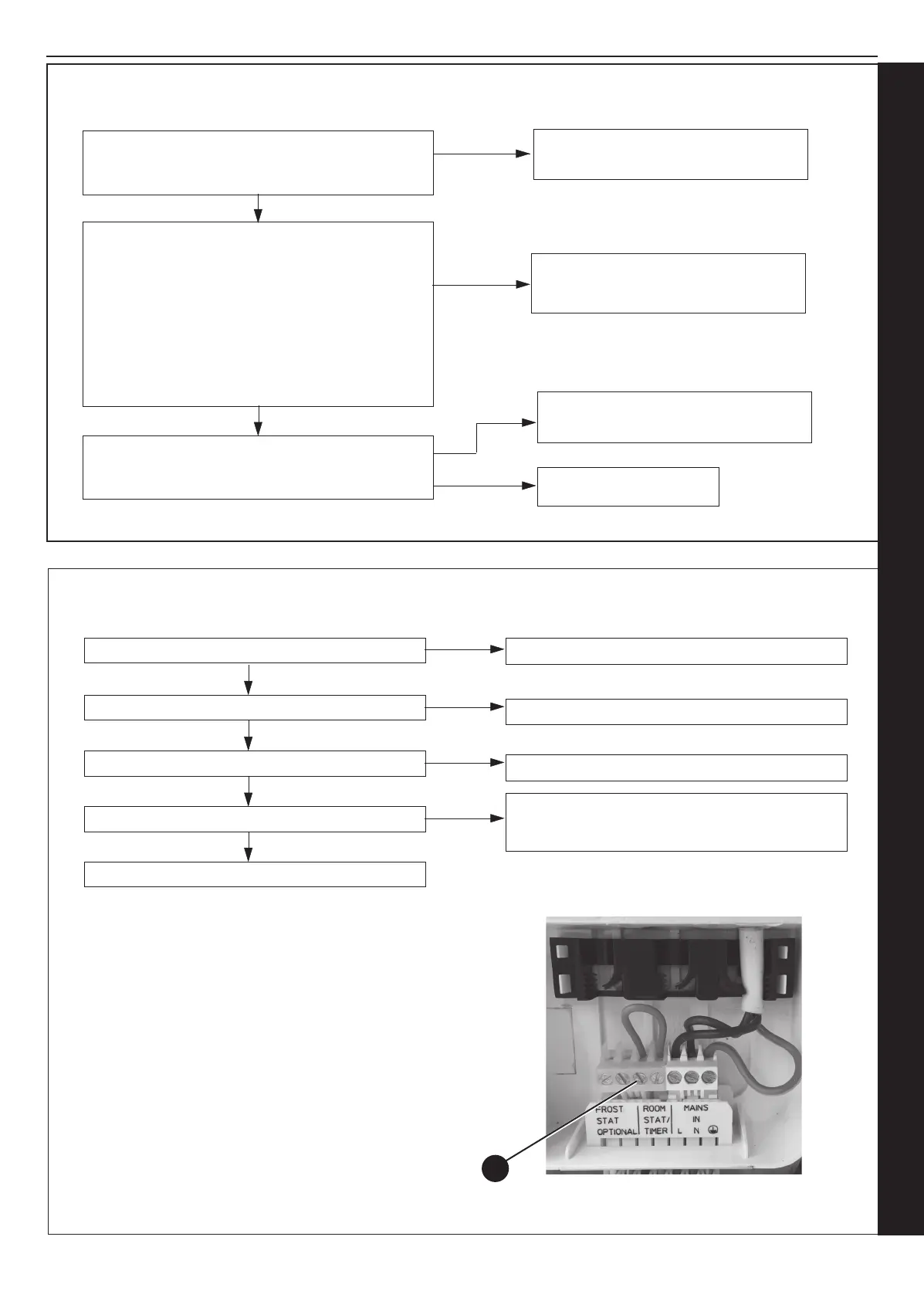
There is no Voltage from the Timer/Room Stat. This
is not boiler fault. Ensure Voltage is supplied to
boiler by rectifying external wiring.
Are the Timer and the Room Thermostat switched on?
Are the Radiator Valves Open?
Is there 230Vac at (A)?
Replace the Diverter Valve Motor
A
 Loading...