1.8 GAS SUPPLY
The local gas supplier should be consulted, at the installation
planning stage, in order to establish the availability of an
adequate supply of gas. An existing service pipe must NOT be
used without prior consultation with the local gas supplier.
The boiler MUST be installed on a gas supply with a governed
meter only.
A gas meter can only be connected by the local gas supplier or
by a Gas Safe Registered Engineer. In IE by a Registered Gas
Installer (RGII).
An existing meter should be checked, preferably by the gas
supplier, to ensure that the meter is adequate to deal with the
rate of gas supply required.
It is the responsibility of the Gas Installer to size the gas
installation pipework in accordance with BS6891:2005. Whilst
the principle of the 1:1 gas valve ensures the Logic range is
able to deliver its full output at inlet pressures as low as 14mb,
other gas appliances in the property may not be as tolerant.
When operating pressures are found to be below the minimum
meter outlet of 19mb these should be checked to ensure this is
adequate for correct and safe operation.
Allowing for the acceptable pressure loss of 1mb across the
installation pipework, it can be assumed that a minimum
permitted operating pressure of 18mb will be delivered to
the inlet of the appliance. (Reference BS 6400-1 Clause 6.2
Pressure Absorption).
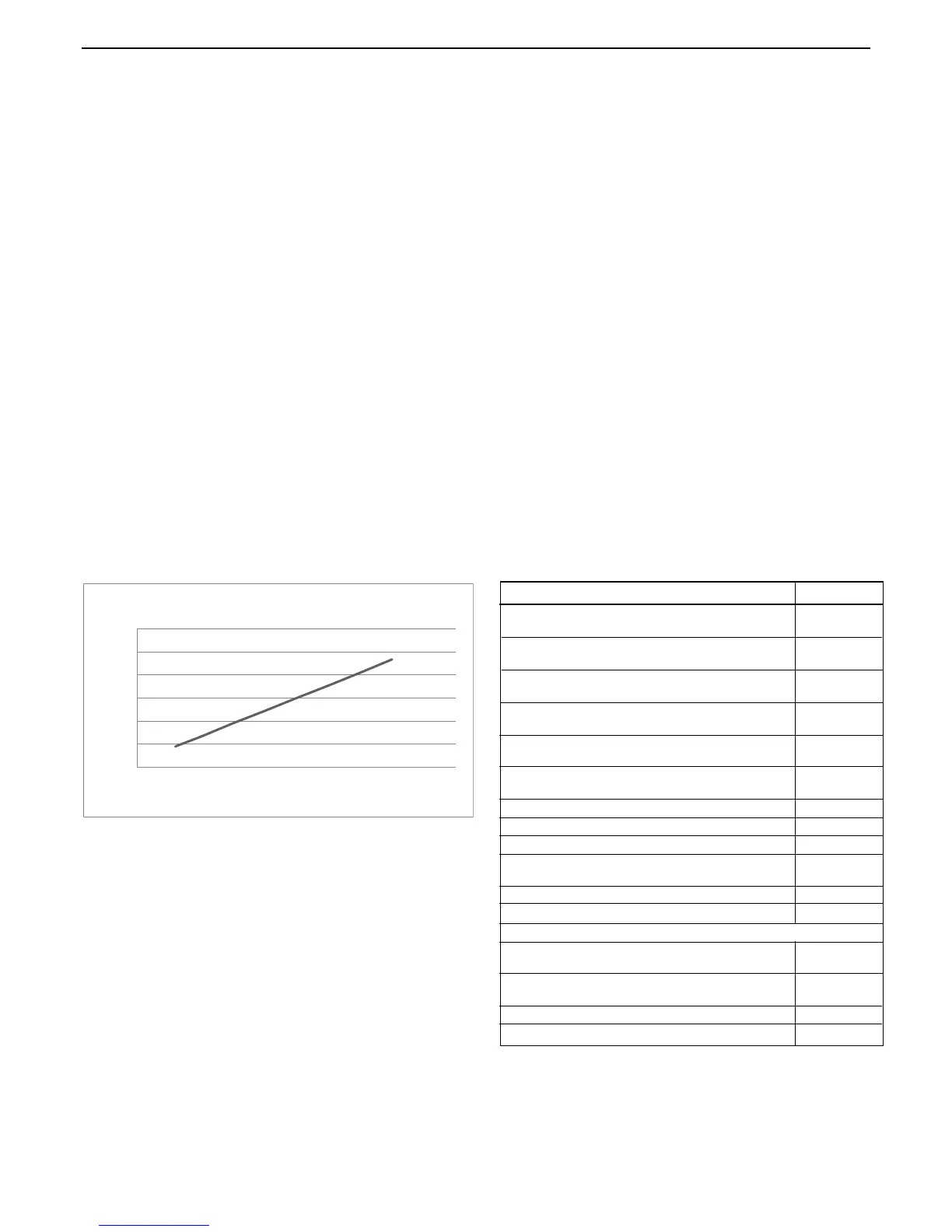
The external gas cock could further reduce the operating
pressure when measured at its test point. The pressure drop is
relative to the heat input to the boiler (kW), refer to graph below.
0
0.5
1
1.5
2
2.5
3
0 10 20 30 40 50
Heat Input to Boiler (kW)
Gas Cock Pressure Drop
IMPORTANT.
Installation pipes must be tted in accordance with BS.6891. In
IE refer to IS.813:2002.
The complete installation MUST be tested for gas tightness and
purged as described in the above code.
1.9 FLUE INSTALLATION
Pluming will occur at the terminal so terminal positions where
this could cause a nuisance should be avoided.
The ue must be installed in accordance with the
recommendations of BS. 5440-1: 2008.
In IE refer to I.S. 813:2002.
The following notes are intended for general guidance:
1. The boiler MUST be installed so that the terminal is exposed
to external air.
2. It is important that the position of the terminal allows the free
passage of air across it at all times.
3.
Minimum acceptable spacing from the terminal to obstructions
and ventilation openings are specied in Table 4.
4. Where the lowest part of the terminal is tted less than 2m
above a balcony, above ground or above a at roof to which
people have access then the terminal MUST be protected by
a purpose designed guard.
Terminal guards are available from boiler suppliers. (Ask
for TFC ue guard model no. K6 - round, plastic coated). In
case of difculty contact:
TFC Group. Tel. + 44 (0) 01732 351 680
Tower House, Vale Rise Fax. + 44 (0) 01732 354 445
Tonbridge. Kent TN9 1TB www.tfc-group.co.uk
Ensure that the guard is tted centrally.
5. The ue assembly shall be so placed or shielded as to
prevent ignition or damage to any part of any building.
6. The air inlet/products outlet duct and the terminal of the
boiler MUST NOT be closer than 25mm to combustible
material. Detailed recommendations on the protection of
combustible material are given in BS. 5440-1:2008.
IMPORTANT. It is essential to ensure, in practice, that products
of combustion discharging from the terminal cannot re-enter the
building or buildings through any openings into the building such
as ventilators, windows, doors, or other sources of natural air
inltration, such as forced ventilation openings etc.
If products of combustion re-entry is identied or suspected this
should be immediately investigated and corrected following the
guidance provided in the current Gas Industry Unsafe Situation
Procedure.
* Only one reduction down to 25mm is allowable per installation
otherwise BS5440-1 2008 dimensions must be followed.
Flue Terminal Positions
Min. Spacing*
1. Directly below, above or alongside an opening
window, air vent or other ventilation opening. 300mm
2. Below guttering, drain pipes or soil pipes. 25mm*
BS5440-1 2008 75mm
3. Below eaves. 25mm*
BS5440-1 2008 200mm
4. Below balconies or a car port roof. 25mm*
BS5440-1 2008 200mm
5. From vertical drain pipes or soil pipes. 25mm*
BS5440-1 2008 150mm
6. From an internal or external corner or to a 25mm*
boundary alongside the terminal. BS5440-1 2008 300mm
7. Above adjacent ground, roof or balcony level. 300mm
8. From a surface or a boundary facing the terminal. 600mm
9. From a terminal facing a terminal. 1,200mm
10. From an opening in a car port
(e.g. door or window) into dwelling. 1,200mm
11. Vertically from a terminal on the same wall. 1,500mm
12. Horizontally from a terminal on the wall. 300mm
Vertical Terminals
13. Above the roof pitch with roof slope of all angles. 300mm
Above at roof. 300mm
14. From a single wall face. 300mm
From corner walls. 300mm
15. Below velux window 2000mm
16. Above or side of velux window 600mm
Table 4 - Balanced Flue Terminal Position
 Loading...


