19
STV50 ed 09/08 VICTRIX 50 Rev. 002
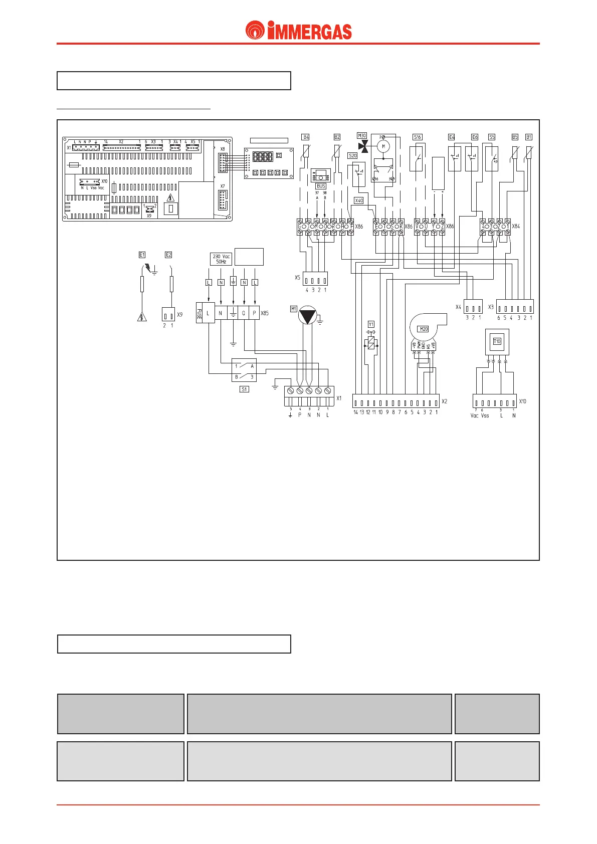
Electrical circuit.
Legend:
B1 - Flow probe
B2 - Domestic hot water probe (option)
B4 - External temperature probe (option)
B5 - Return probe
E1 - Ignition electrode
E2 - Detection electrode
E4 - Safety thermostat
E6 - Flue thermostat
M1 - Pump
M20 - Fan
M30 - ree-way valve (option)
S1 - Main switch
S5 - System pressure micro switch
S16 - Summer switch (not provided to Immergas)
S20 - Room thermostat (option)
T10 - Low voltage transformer
X40 - Room thermostat jumper
Y1 - Gas valve (24 V DC)
(from the serial number 3918687)
e VICTRIX 50 electrical circuit is connected to a microproc-
essor controlled p.c.b. that controls generator functions.
230 V AC circuit.
Safety devices and controls.
Some of the device on the circuit work at mains voltage (230
V AC) while others work at a low voltage.
is interrupts power to the circuit when power input is over 2 A.
It is mounted on the integrated board.
Line fuse (board)
(F1)
2 AF 250 V fuse
is interrupts power to the circuit when power input is over 2 A.
It is mounted on the boiler terminal block.
Line fuse (terminal block)
(F2)
2 AF 250 V fuse
Black
Black
Black
Black
Black
Black
Black
Red
Red
Red
Red
Red
Red
Black
Black
Blue
Blue
Blue
Blue
Brown
Brown
Brown
Brown
Brown
Y/G
Y/G
White
White
White
White blue
White brown
White brown
White brown
White blue
White
White
Wh.
Grey
Grey
Grey
Grey
Grey
Purple
Purple
Purple
Purple
Orange
Orange
Black
D.H.W.
C.H.
DISPLAY BOARD
Analogic input
0-10 V
External
circulating
pump Max. 1 A
F3
F1
Technical Documentation
Technical Documentation
 Loading...