22
STV50 ed 09/08 VICTRIX 50 Rev. 002
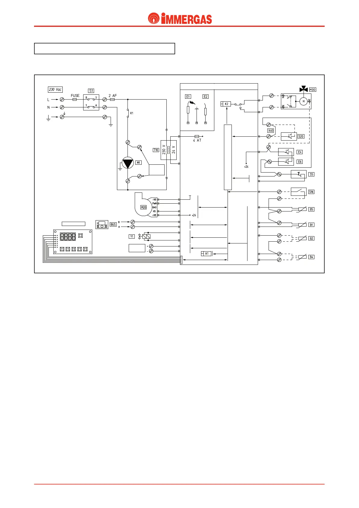
External
pump
MAX 1 A
IGNITION AND
DETECTION ELECTRODE
SAFETY EXTRA-LOW
VOLTAGE CIRCUIT
LOGIC-CONTROLS MICROPROCESSOR
Central Heating
DHW.
DISPLAY BOARD
ANALOG
INPUT
Electric circuit.
Central heating mode.
Operating with room thermostat.
e main switch (S1) at ON position powers the integrated
P.C.B. and enables functioning in CH mode.
If the contact of the system pressure switch (S5) is closed
(pressure detected in the primary circuit at minimum value),
after having obtained consent from the safety thermostat (E4),
the ue safety thermostat (E6) and on closure of the room
thermostat contact (S20), the board powers the boiler pump
(M1) by means of relay K1.
In the meantime the adjustment circuit powers the fan (M20)
and manages its speed.
If the temperature detected by the NTC ow probe (B1) is
lower than parameter N° 4 "Central Heating ow tempera-
ture" set, the board starts the ignition cycle controlling, rst
the ignition electrode (E1) and successively, both coils of the
gas valve (Y1).
e ignition of the burner is detected by the P.C.B. by means
of the ionisation electrode (E2).
Operating with thermoregulation.
Using the cascade and zone regulator, the functioning request
is managed by the regulator itself, which depending on the
settings made, interacts with the boiler integrated P.C.B. by
means of BUS cables.
Technical DocumentationTechnical Documentation
 Loading...