21
STVZ ed 02/06 VICTRIX Zeus
Technical Documentation
Technical Documentation
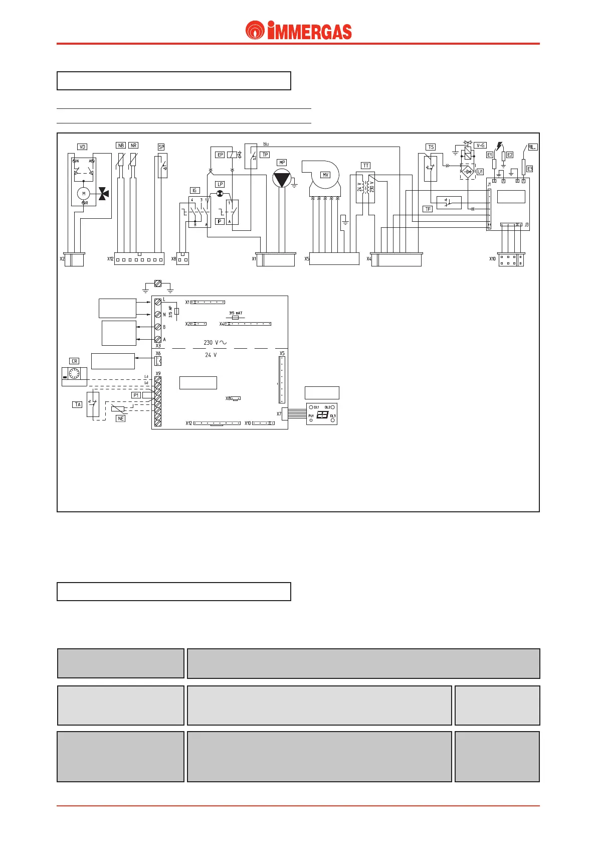
Electrical circuit.
e VICTRIX Zeus electrical circuit is completely connected
to a microprocessor controlled card board that controls gen-
erator functions.
230 V AC circuit.
Safety devices and checks.
Some of the devices of control and safety on the circuit operate
at mains voltage (230 V AC) while the others at low voltage.
Legend:
CR - Remote control (optional)
CZ - Zone control unit (optional)
DL1 - Heating function Led
DL2 - D.h.w. function Led
DL3 - Flame detection Led
E1-E2 - Ignition electrodes
E3 - Detection electrode
EP - Maximum drawing solenoid valve
F - Line fuse
IG - Rotating main switch
IP - Maximum drawing switch
LP - Maximum drawing light
MP - Circulator
MV - Fan
NB - Storage tank NTC probe
NE - External sensor (optional)
NR - Heating NTC probe
P1 - Room thermostat bridge or Remote Control
PU1 - Block reset
SP - Pump micro flow switch
T - Transformer fuse
TA - On/Off room thermostat (optional)
TF - Fume thermostat
TP - Max drawing limit thermostat
TS - Overtemperature safety thermostat
TT - Voltage transformer
U1 - Rectifier inside the V.G. connector
VD - 3-way electric valve
V-G - Gas valve
(from the serial number 2753798 for VICTRIX Zeus 20)
(from the serial number 2731813 for VICTRIX Zeus 27)
is detects ignition of the burner by whose flame it is covered.
It is connected to the ignition board detection circuit.
Detection electrode
(E3)
is cuts power to the circuit when the current absorbed is over 3.15 A.
It is fitted on the modulating control board.
Line fuse
(F)
3.15 AF fuse
250 V
is cuts power to the transformer (230V/24V) of the low-voltage circuit
when the current absorbed is over 315 mA .
It is fitted on the modulating control board.
Transformer fuse
230V / 24V
(T)
315 mA fuse
250 V

 Loading...