INFOSEC UPS SYSTEM – 4 rue de la Rigotière – 44700 Orvault – France – www.infosec-ups.com
Hot Line Tel : +33 (0)2 40 76 15 82 – fax : +33(0)2 40 94 29 51 – hotline@infosec.fr – 04 09 AA XX 201 19
13
3.4.2 UPS Connection
1. See the following chart for input and output cable section & breaker calibration
Note: Do not use the wall receptacle as the input power source for the UPS, as its
rated current is less than the UPS’s maximum input current. The receptacle may be
burned and destroyed.
INPUT OUTPÜT
UPS Model
BREAKER CABLE BREAKER CABLE
E6 LCD 5000 RT 2 x 32 A 3 x 6 mm² 2 x 25 A 3 x 4 mm²
E6 LCD 6000 RT 2 x 40 A 3 x 6 mm² 2 x 32 A 3 x 6 mm²
E6 LCD 8000 RT 2 x 50 A 3 x 10 mm² 2 x 40 A 3 x 6 mm²
E6 LCD 10 K RT 1/1 2 x 63 A 3 x 10 mm² 2 x 50 A 3 x 10 mm²
E6 LCD 10 K RT 3/1 4 x 63 A 5 x 10 mm² 2 x 50 A 3 x 10 mm²
WARNING: If the connecting of neutral wire (N) and Line wire (L) is in order,
the UPS do not change neutral rate of installation. A circuit breaker connected
before the UPS will operate for an insulation fault after the UPS.
Sensibility of the circuit breaker takes into account the UPS current leak (about
15mA) and connected computers. We recommend selective 300mA.
2. If the UPS is DIM (Dual Input) type whose Utility and Bypass Sources are the same, L11
and L12 would have to be shorted for 1-phase input model.
3. If the UPS is SIM (Single Input) type, only AC source can be supplied to UPS from L12-
N1 terminal for 1-phase input model and R-S-T-N1 terminal for 3-phase input model.
4. When the Isolation transformer is NOT installed into the tower type UPS, the UPS
output terminals will be L21-N22.
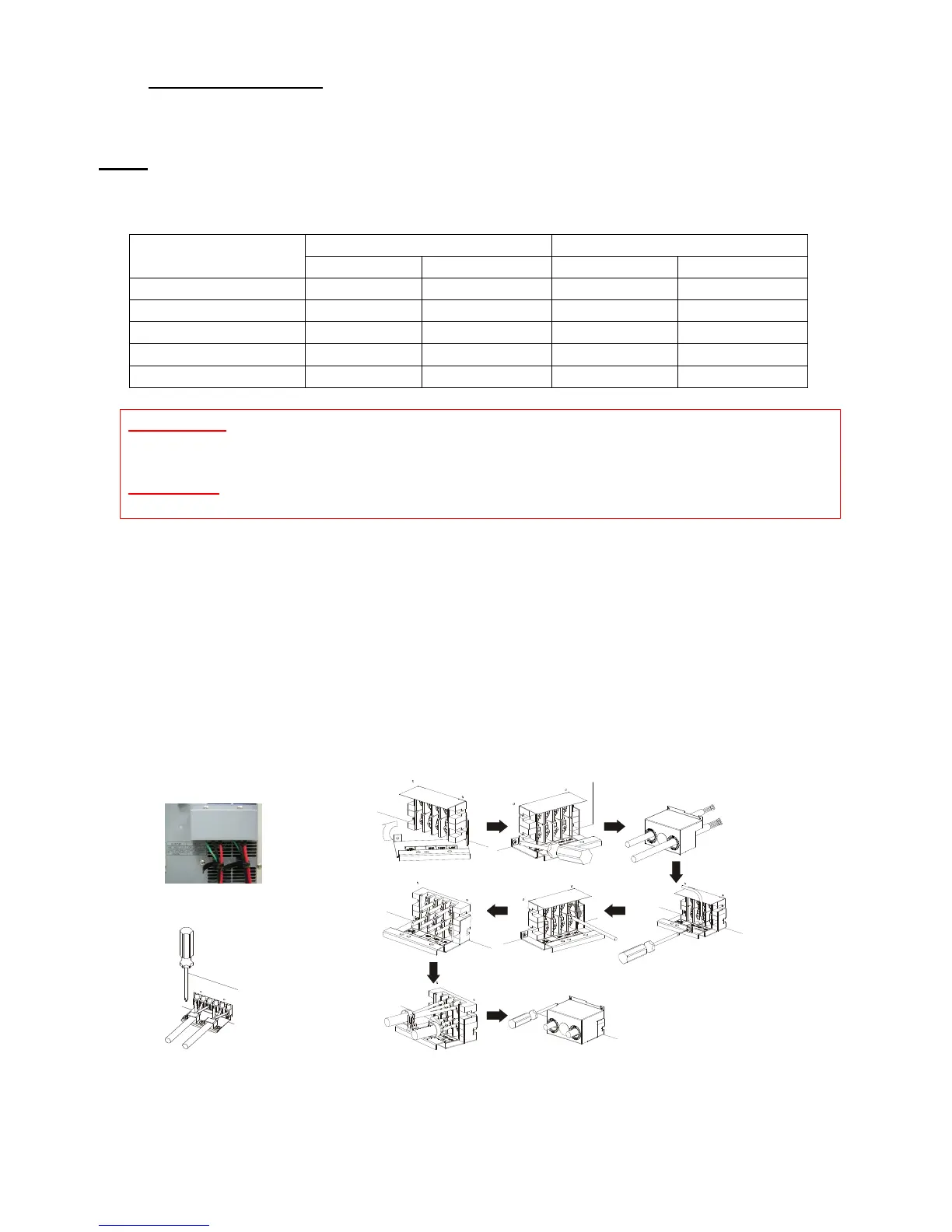
Use Mounting Cable Tie to fix cables.
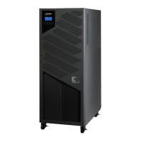
6/8000VA model
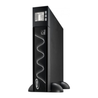
5000VA model
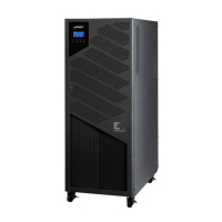
10KVA model
 Loading...