INFOSEC UPS SYSTEM – 4 rue de la Rigotière – 44700 Orvault – France – www.infosec-ups.com
Hot Line Tel : +33 (0)2 40 76 15 82 – fax : +33(0)2 40 94 29 51 – hotline@infosec.fr – 04 09 AA XX 201 19
23
5. Bundled Software Installation Guide
5.1 Hardware Installation
1. Connect the male connector of RS232 cable to the UPS communication port.
2. Connect the female connector of the RS232 cable to a dedicated RS232 port of the
computer.
3. For optional interface cards, you may refer to Chapter 6 for installation.
5.2 Software Installation
Please refer to the user’s manual of the software for installation.
6. Customer Options Slots
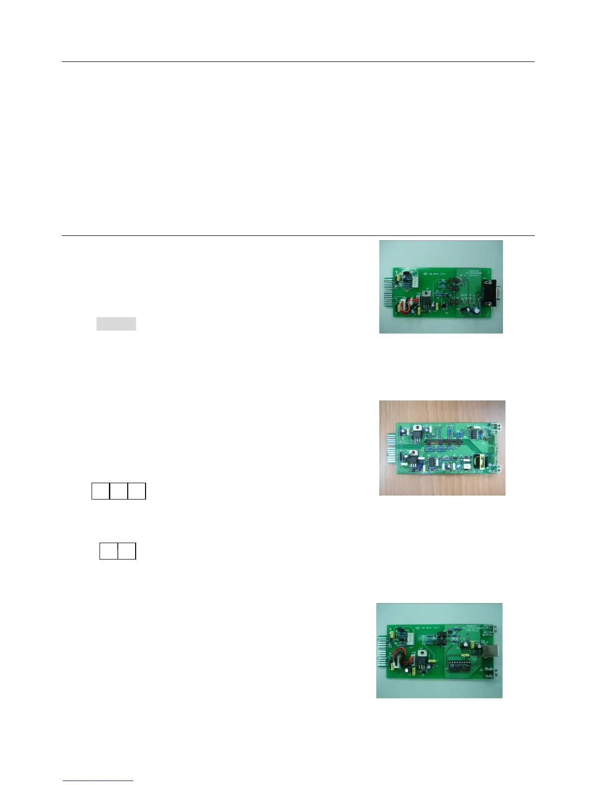
6.1 R2E (2nd RS-232) card
CN1 is for RS232 DB9.
For communication protocol, please refer to Chapter
0(2.4.1)
Installation Position: slot1 (CHA-CN4) or slot 2(CHB-
CN5).
6.2 RSE (RS-485) card
CN1 is for the function of the terminal resistor.
Short pin1-2 to enable the function and short pin2-3
to disable it.
CN2 for RS485 and CN3 for remote power.
Definition
Installation Position: slot1.
6.3 USE(USB) card
CN1 for USB.
Definition
Comply with USB version 1.0,1.5Mbps
Comply with USB HID Version 1.0.
The Pin Assignments of the USE card:
Installation Position: slot1(CHA-CN3) or slot 2(CHB-CN4).
1
2
CN3
1
2
3
CN2
1 Ground
2 A/Data+
3 B/Data-
1 AC+
2 AC-
 Loading...