- 19 -
Installation and Wiring
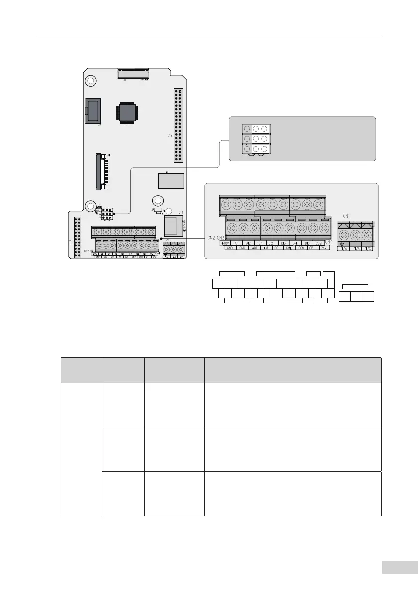
2.2.4 Control Circuit Terminals
+10V AI1 AI2 DI1 DI2 DI3 DI4 DI5 COM
GND GND AO1 FM DO1 CME COM OP +24V
T/A T/B T/C
Analog input and
power supply
Logic input Pulse input Powe r supply
Relay output
Analog output and
analog terminal
Pulse output and open-
collector output
Logic public terminal
and power supply
AO1 output selection: voltage output by default
J7
J9
J10
I V
AI2 input impedance selection: 500 Ω by default, 250 Ω
selectable
AI2 input selection: voltage input by default
Figure 2-7 Control circuit terminal arrangement
Table 2-2 Description of control circuit terminals
Type
Terminal
Mark
Terminal Name Description
Power
supply
+10 V-GND
+10 V power
supply
Provides +10 V power supply to an external unit.
Its maximum output current is 10 mA.
Generally used to supply an external
potentiometer of 1 to 5 kΩ.
+24V-COM
+24 V power
supply
Provides +24 V power supply to an external
unit. Generally used for power supply for DI/DO
terminals and external sensors.
Maximum output current: 200 mA
[1]
.
OP
Input terminal
for external
power supply
Connected to +24 V by default.
When DI1 to DI5 need to be driven by external
signals, OP must be disconnected from + 24 V and
connected to an external power supply.
 Loading...