- 21 -
Installation and Wiring
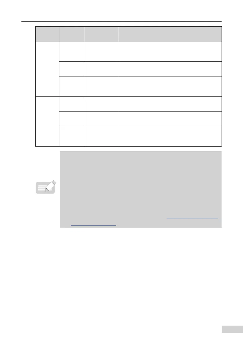
Type
Terminal
Mark
Terminal Name Description
Auxiliary
interfaces
J13
Extension card
interface
Interface for the 28-core terminal and optional
cards (I/O extension card, PLC card, and various
bus cards).
J4
PG card
interface
The open-collector, dierential, and resolver
interfaces are selectable options.
J11
External
operating panel
interface
Connected to an external operating panel.
Jumper
[3]
J7
AO1 output
selection
Either a voltage or a current output. Voltage
output by default.
J9
AI2 input
selection
Either a voltage or a current input. Voltage input
by default
J10
AI2 input
impedance
selection
Either 500 Ω or 250 Ω input. 500 Ω input by default
◆ [1] When the ambient environment is above 23 ºC the output current
must be de-rated for 1.8 mA per 1ºC rise. The maximum output current
is 170 mA at 40 ºC. When OP is shorted to 24 V, the current of the DI must
also be considered.
◆ [2] Select 500 Ω or 250 Ω input impedance according to the with-load
capacity of signal source. For example, if 500 Ω is selected, the maximum
output voltage of signal source cannot be smaller than 10 V so that AI2 can
measure 20 mA current.
◆ [3] For positions of jumpers J7, J9 and J10, see
"Figure 2-7 Control circuit
terminal arrangement"
.

 Loading...