PCI Express* Add-in Card Considerations
336521 23
3. Rest-of-Platform power demand
Rest-of-Platform(ROP) collectively includes anything in a system (memory, storage,
motherboard, peripherals, etc.) not including the PCIe Add-in Cards or CPU. Table 3-2
provides examples that generally balance these three power demands to obtain an
overall PSU power rating. The PCIe power entries in the table are standard power
levels for PCIe Add-in Cards defined in the PCIe CEM 5.0 Specification. As a
consequence of the introduction of 450 W and 600 W Card power levels, the wide
range of possible PCIe card power demands plays a dominant role in setting total
platform power supply ratings.
These configurations will also serve as test cases for evaluating power supply
excursions. The peak power demands of the PCIe Add-in Cards at each power level
can guide the peak power demands of the PSU.
In cases where a PCIe Add-in Card has a sustained power not listed, use these values
as a minimum value for all cards up to these power levels. The table below is seen as
a minimum power level based on Rest of Platform (ROP) power. The ROP assumptions
are shown in Table 3-2 below. If a system designer plans more ROP power, the overall
platform power budget for a system must be increased. If a system designer plans
less ROP power, then the PSU size can also decrease. In the case of ROP values lower
than what is shown in Table 3-2, the calculations should be done for Peak Power
Requirement for this specific system. If the Peak Power requirements for this specific
system exceed the values shown in Table 3-3
than a PSU with support for higher peak
power levels would be needed.
The CPU continuous power comes from Table 2-1, taking the current value and
multiplying by 11.2 Volts to create a power value and round up slightly. The CPUs
used in these examples are the 65w TDP for the first row and 125w TDP for all other
rows.
This is a recommendation for a Power Budget and guidance that is needed to define
PSU Peak Power Excursion levels. These power budgets also assume only one PCIe
Add-in Card will use these power excursions. If more than one PCIe Add-in Card is
installed in the system, then the system designer needs to verify the power supply
can provide enough power for all components in the system including the Peak Power
Excursions of all components. This industry standard PSU Design Guide does not
provide a standard definition for that type of system design.
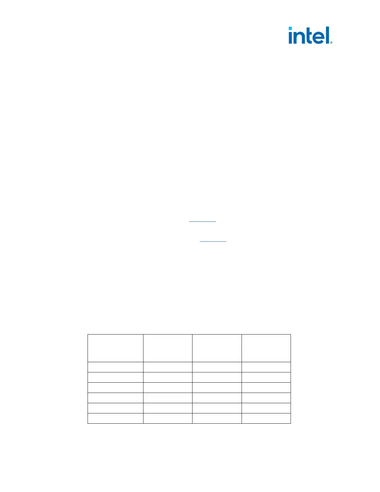
Table 3-2: PCIe* AIC and PSU Power Budget used for Peak Power Excursion Test Cases
PCIe* AIC
Power
(W)
CPU
Continuous
Power
(W)
Rest of
Platform
(W)
PSU Rated
PSU Size
(W)
75 275 100 450
150 300 100 550
225 300 125 650
300 300 150 750
450 300 250 1000
600 300 300 1200
• Rest of Platform power here will not apply to all systems.
 Loading...


