Mechanical
50 336521
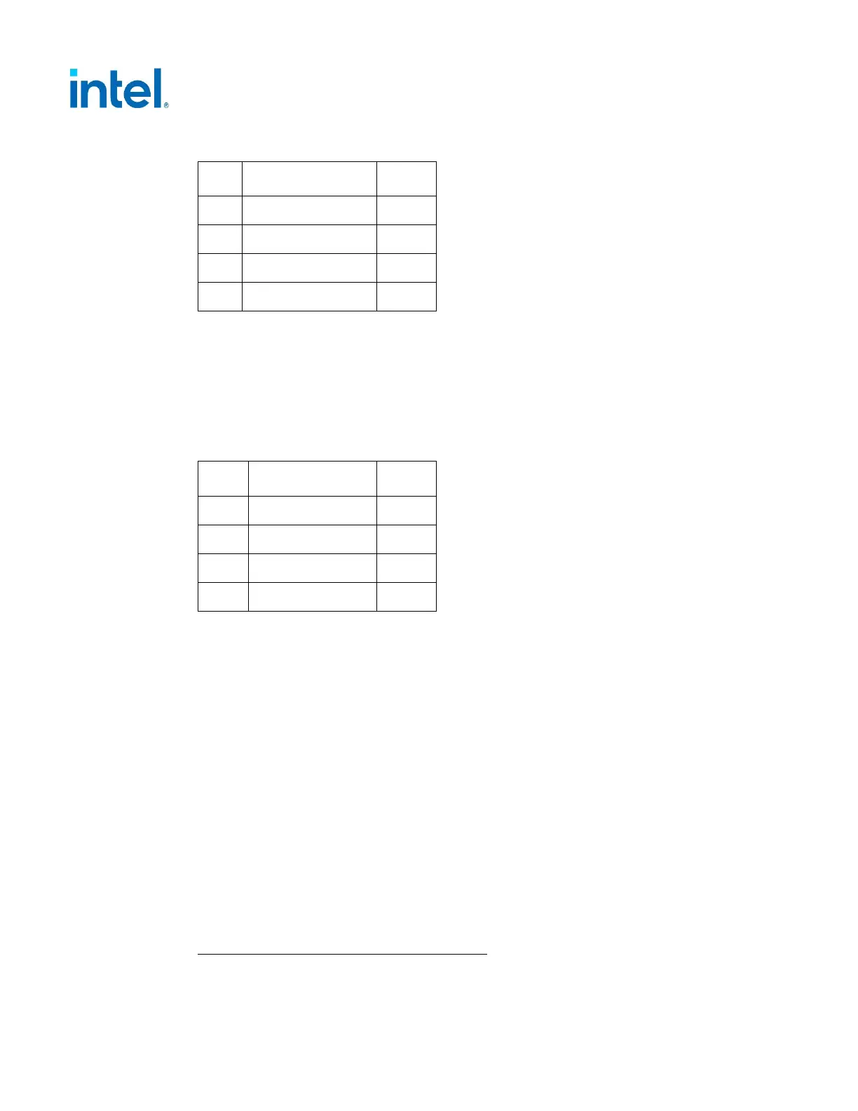
Table 5-2: Peripheral Connector Pin-out
Pin Signal Color
1
1
+12V1 DC Yellow
2
COM Black
3
COM Black
4
+5 VDC Red
NOTE: 18 AWG wire.
5.2.2.3 Floppy Drive Connector – Do Not Include (For Historical
Reference Only)
Connector: AMP* 171822-4 or equivalent.
Table 5-3: Floppy Connector Pin-out
Pin Signal Color
1
1
+5V DC Red
2
COM Black
3
COM Black
4
+12V1 DC Yellow
NOTE: 20 AWG wire.
5.2.2.4 PCI-Express* (PCIe*) Add-in Card Connectors (Recommended)
These are optional connectors for the power supply to support additional power
needed by any PCI Express** Add-in Card (AIC). The most common PCIe* Add-in
Card that uses these connectors are discrete graphics cards. The PCIe* CEM
Specification defines different connectors based on the power used by the Add-in Card
which can range from 75 watts up to 600 watts.
5.2.2.4.1 PCI Express* (PCIe*) 2x3 Auxiliary Power Connector
(Recommended)
The 2x3 Power Connector is designed to provide 75 watts to the PCIe* Add-in Cards
and has the following requirements:
• Current Rating: 8.0 A/pin/position maximum to a 30 °C T-Rise above ambient
temperature conditions at +12 VDC, all six contacts energized.
• Mated Connector Retention: 30.00 N minimum when plug pulled axially.
Cable Assembly Contact and Housing Details:
• Housing Material: Thermoplastic
 Loading...


