PCI Express* Add-in
Card Considerations
26 336521
tolerance required to the PCIe* Add-in Card at both the motherboard edge card
connector and Auxiliary Power connectors. Each Auxiliary Power Connector must have
voltage pins that belong to the same +12V power converter, if multiple voltage rails
exist from the PSU.
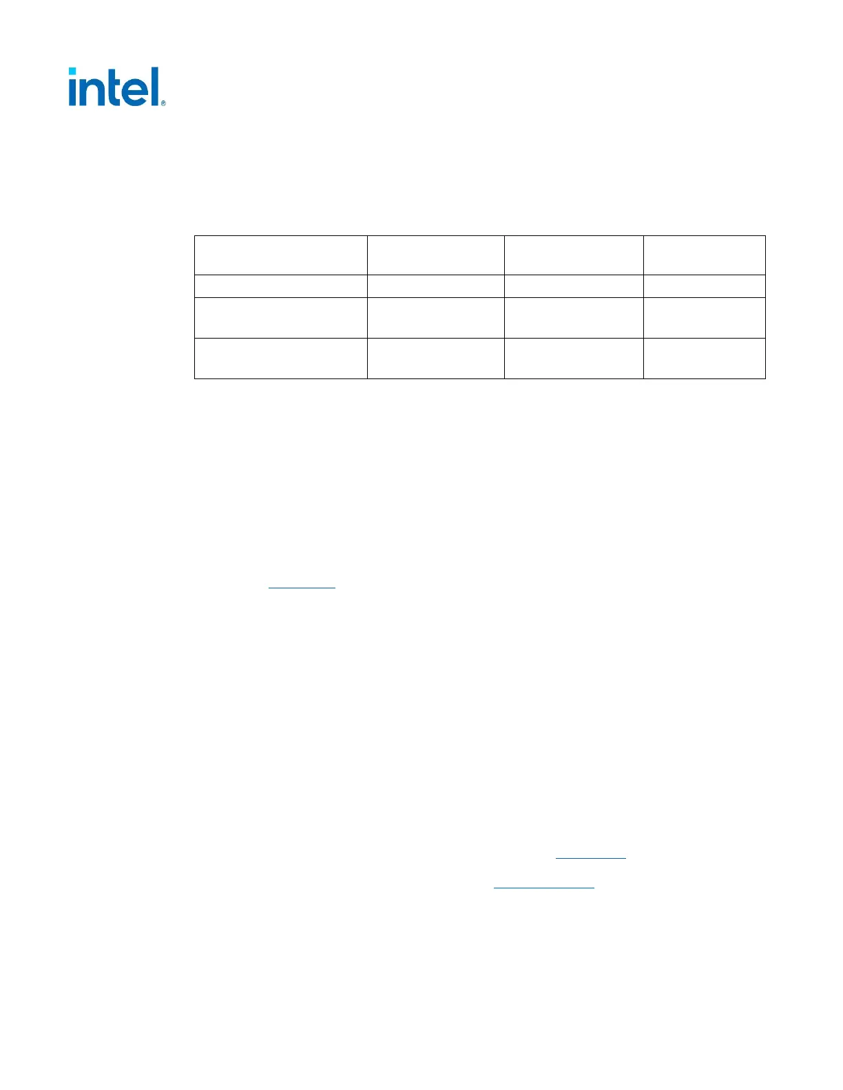
Table 3-5: Auxiliary Power Connectors Power Supply Rail Requirements - +12V Only
+12V Power Rail
Characteristic
2x3 Connector 2x4 Connector
12VHPWR
Connector
Sustained Power
2, 4, 5
75 Watts 150 Watts 600 Watts
+ 12 V
Voltage Range
+5% / -8% +5% / -8% +5% / -8%
Current
3, 4, 5
(Max RMS)
6.75 Amps 13.5 Amps 55 Amps
1
NOTES:
1. The maximum current slew rate for the 12VHPWR connector interface shall be no
more than 5.0 A/µs.
2. Maximum sustained power is an average power in any continuous 1 second interval
3. Maximum of root-mean-square (RMS) of current in any continuous 1 second
interval
4. The main reference limit is the maximum allowed sustained power per connector
and Add-in Card type. Add-in Card and System must concurrently comply with all
power and voltage and current requirements in this table for the applicable
connector and other requirements in this specification for the Add-in Card type.
5. Maximum instantaneous and other excursions exceeding these limits are defined in
Section 3.1
of this document.
3.3 PCIe* Add-in Card Auxiliary Power Connectors
Sideband Signals
The new 12VHPWR connector has 4 sideband signals defined that communicate
between the Power Supply and the PCIe* Card. Two of these sideband signals are
required with the connector and two of them are optional from the Power Supply. The
four sideband signals are:
• SENSE0
• SENSE1
• CARD_PWR_STABLE
• CARD_CBL_PRES#
For the most up to date and detailed description, refer to Section 5.3 – Optional
Sideband Signal in the PCI Express* Card Electromechanical Specification,
Revision 5.0. That document is available from
www.pcisig.com.
 Loading...


