Electrical
40 336521
Some scenarios like USB Power Charging in ALPM could require more current on the
5VSB rail.
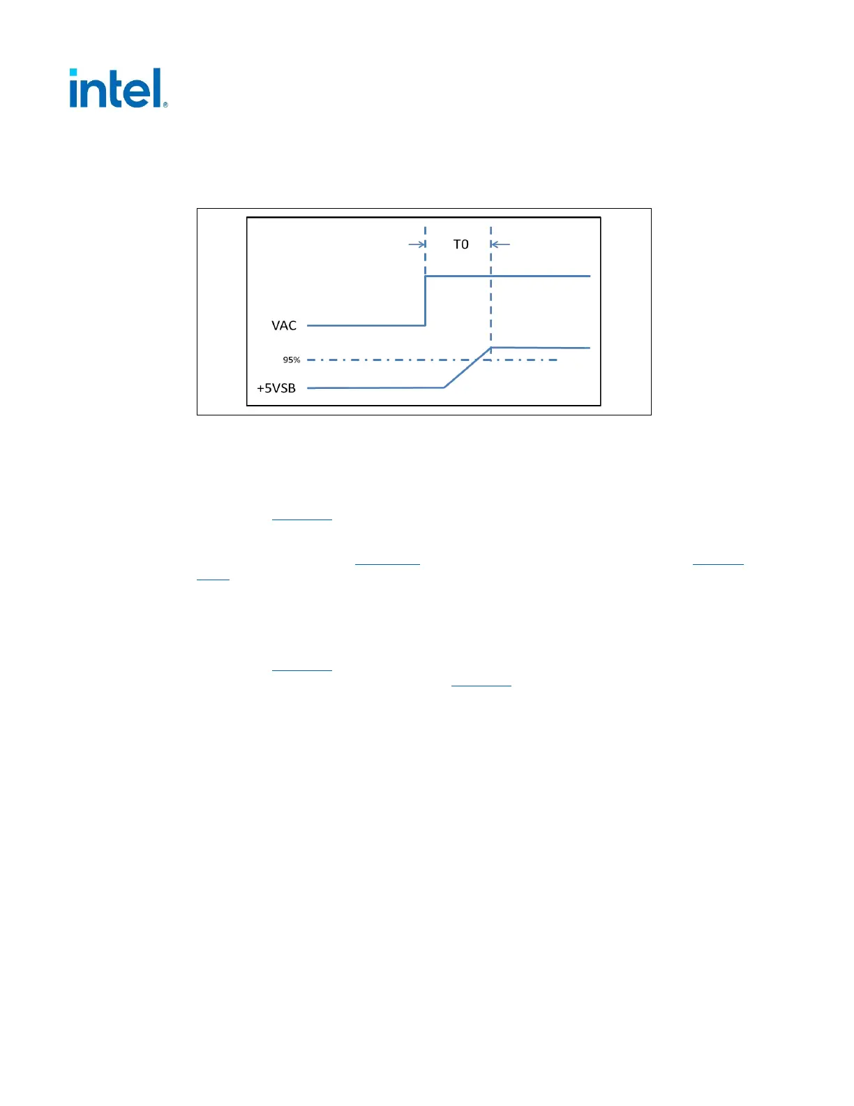
Figure 4-5 +5VSB Power on timing versus VAC
4.3.5 Power-On Time – REQUIRED
The power-on time is defined as the time from when PS_ON# is pulled low to when
the +12 VDC, +5 VDC, and +3.3 VDC outputs are within the regulation ranges
specified in Table 4-2
. The power-on time shall be less than 500 ms (T1 < 500 ms).
+5VSB shall have a power-on time of two second maximum after application of valid
AC voltages as shown in Figure 4-5
. The 5VSB power on time is T0 as listed in Section
4.3.4.
4.3.6 Rise Time – REQUIRED
The output voltages shall rise from 10% of nominal to within the regulation ranges
specified in Table 4-2
within 0.2 ms to 20 ms (0.2 ms ≤ T2 ≤ 20 ms). The total time
for Rise time of each voltage is listed in Table 4-9 as T2.
There must be a smooth and continuous ramp of each DC output voltage from 10% to
95% of its final set point within the regulation band, while loaded as specified.
The smooth turn-on requires that, during the 10% to 95% portion of the rise time, the
slope of the turn-on waveform must be positive and have a value of between 0 V/ms
and [Vout, nominal / 0.2] V/ms. Also, for any 5 ms segment of the 10% to 95% rise
time waveform, a straight line drawn between the end points of the waveform
segment must have a slope ≥ [Vout, nominal / 20] V/ms.
 Loading...


