Mechanical
336521 47
5 Mechanical
This chapter contains mechanical guidelines that apply to desktop power supplies
regardless of form factor. For form factor specific design guides refer to Chapter 11
through Chapter 16.
5.1 Labeling and Marking - RECOMMENDED
The following is a non-inclusive list of suggested markings for each power supply unit.
Product regulation stipulations for sale into various geographies may impose
additional labeling requirements.
Manufacturer information: manufacturer's name, part number and lot date code,
etc., in human-readable text and/or bar code formats.
Nominal AC input operating voltages (100-127 VAC and 200-240 VAC) and
current rating certified by all applicable safety agencies.
DC output voltages and current ratings.
Revision number of the ATX, SFX, etc. specification that the power supply
meets.
Access warning text (“Do not remove this cover. Trained service personnel only. No
user serviceable components inside.”) must be in English, German, Spanish, French,
Chinese, and Japanese with universal warning markings.
Power Supplies are recommended list the supported Required or Recommended
Timing values (T1 and T3) in product documentation. There are two levels of timing
for T1 and T3 a power supply can support as detailed in Figure 4-2. This will help
system integrators and end users know the T1 and T3 timing values.
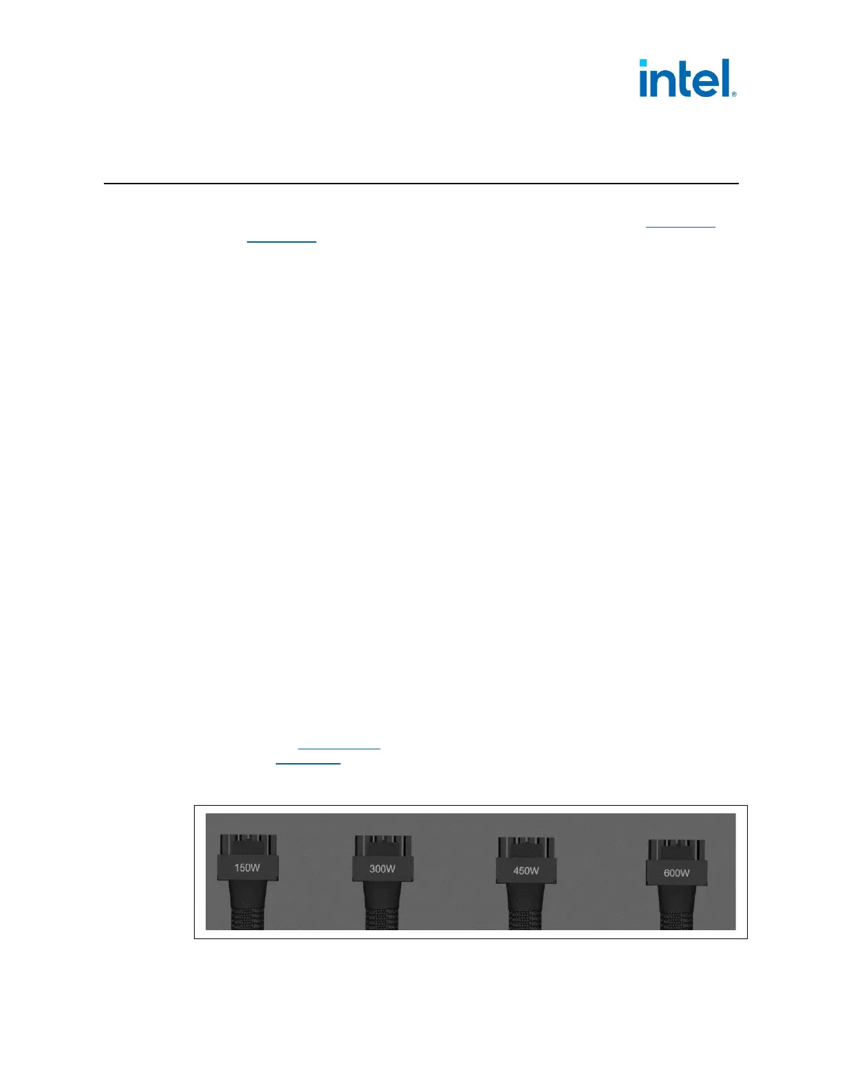
12VHPWR connector/cable harnesses that are hard-wired to the power supply shall be
labeled indicating the maximum power supported according to the Sense0/1
encoding implemented for each connector. If the Sense lines are dynamic (can
change in standby mode only), the product documentation must describe the power
levels supported based on the number of PCIe* Add-in Cards connected. Sense0/1
are described in Section 3.3.1
of this document. An example of these labels are
illustrated in Figure 5-1 below.
Figure 5-1: 12VHPWR Connector Labeling Example
 Loading...


