Intel Desktop Board D850GB Technical Product Specification
70
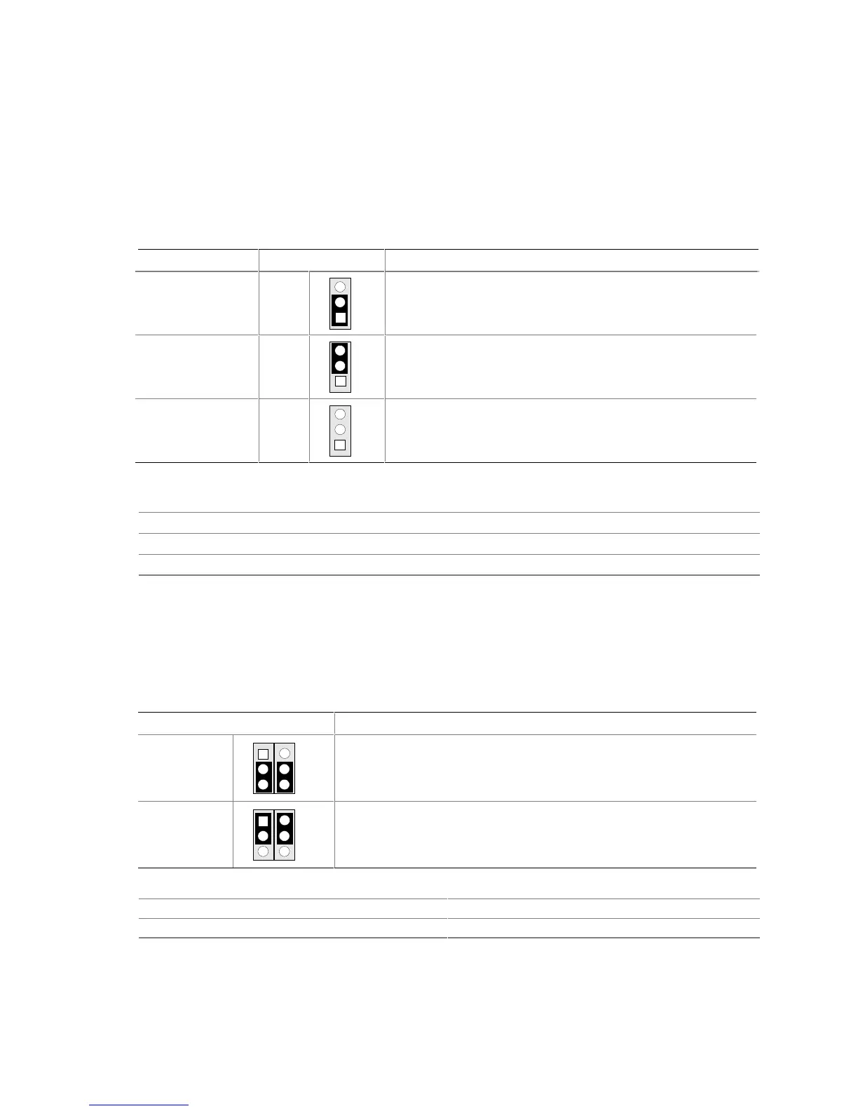
2.9.1 BIOS Setup Configuration Jumper Block
This 3-pin jumper block determines the BIOS Setup program’s mode. Table 49 describes the
jumper settings for the three modes: normal, configure, and recovery. When the jumper is set to
configuration mode and the computer is powered-up, the BIOS compares the processor version and
the microcode version in the BIOS and reports if the two match.
Table 49. BIOS Setup Configuration Jumper Settings (J8C2)
Function/Mode Jumper Setting Configuration
Normal
1-2
1
3
The BIOS uses current configuration information and
passwords for booting.
Configure
2-3
1
3
After the POST runs, Setup runs automatically. The
maintenance menu is displayed.
Recovery
None
1
3
The BIOS attempts to recover the BIOS configuration. A
recovery diskette is required.
For information about Refer to
How to access the BIOS Setup program Section 4.1, page 89
The maintenance menu of the BIOS Setup program Section 4.2, page 90
BIOS recovery Section 3.7, page 85
2.9.2 USB Port 2 Routing Jumper Block
This 6-pin jumper block routes the signals of USB port 2. Table 50 describes the jumper settings
for USB port 2. Figure 13 shows the location of the Front Panel USB connector.
Table 50. USB Port 2 Routing Jumper Settings (J8D1)
Jumper Setting Configuration
2-3 and 5-6
1
3
4
6
USB port 2 signals are routed to the Front Panel USB connector.
1-2 and 4-5
1
3
4
6
USB port 2 signals are routed to the CNR connector.
For information about Refer to
The location of the Front Panel USB connector Figure 12, page 65
The location of the CNR connector Figure 11, page 59
 Loading...