Mechanical Drawings
128 Thermal and Mechanical Design Guidelines
Appendix H Mechanical Drawings
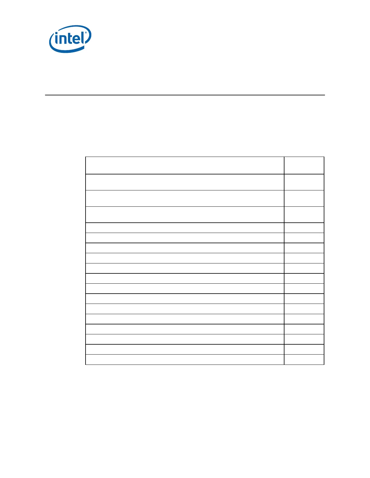
The following table lists the mechanical drawings included in this appendix. These
drawings refer to the reference thermal mechanical enabling components for the
processor.
Note: Intel reserves the right to make changes and modifications to the design as
necessary.
Drawing Description Page
Number
ATX/µATX Motherboard Keep-out Footprint Definition and Height Restrictions
for Enabling Components - Sheet 1
129
ATX/µATX Motherboard Keep-out Footprint Definition and Height Restrictions
for Enabling Components - Sheet 2
130
ATX/µATX Motherboard Keep-out Footprint Definition and Height Restrictions
for Enabling Components - Sheet 3
131
. BTX Thermal Module Keep Out Volumetric – Sheet 1 132
BTX Thermal Module Keep Out Volumetric – Sheet 2 133
. BTX Thermal Module Keep Out Volumetric – Sheet 3 134
BTX Thermal Module Keep Out Volumetric – Sheet 4 135
BTX Thermal Module Keep Out Volumetric – Sheet 5 136
ATX Reference Clip – Sheet 1 137
ATX Reference Clip - Sheet 2 138
Reference Fastener - Sheet 1 139
Reference Fastener - Sheet 2 140
Reference Fastener - Sheet 3 141
Reference Fastener - Sheet 4 142
Intel
®
D60188-001 Reference Solution Assembly 143
Intel
®
D60188-001 Reference Solution Heatsink 144
Intel
®
E18764-001 Reference Solution Assembly 145
 Loading...