Case Temperature Reference Metrology
Thermal and Mechanical Design Guidelines 97
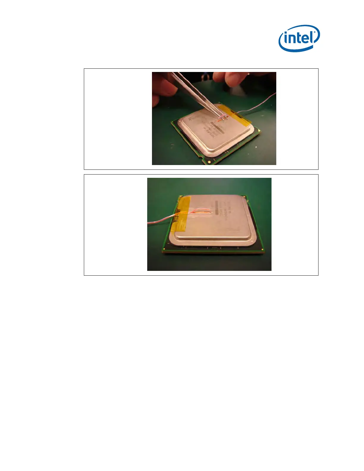
Figure 7-19. Thermocouple Bead Placement
(A)
(B)
16. Place the package under the microscope to continue with process. It is also
recommended to use a fixture (like processor tray or a plate) to help holding the
unit in place for the rest of the attach process.
17. While still at the microscope, press the wire down about 6mm [0.125”] from the
thermocouple bead using the tweezers or your finger. Place a piece of Kapton*
tape to hold the wire inside the groove (
Figure 7-20). Refer to Figure 7-21 for
detailed bead placement.
 Loading...