A THEORY OF OPERATION
4-5
4.4.3.1 Parallel Port
The parallel port is a full implementation of a Centronix-compatible receive-only port. A program sets
up and reads the parallel port by reading or writing three registers:
The parallel port generates an interrupt when the PSTROBE
or the PPINIT signal is asserted from an
external transmit port. The parallel port interrupts are cleared after a read from the parallel data register.
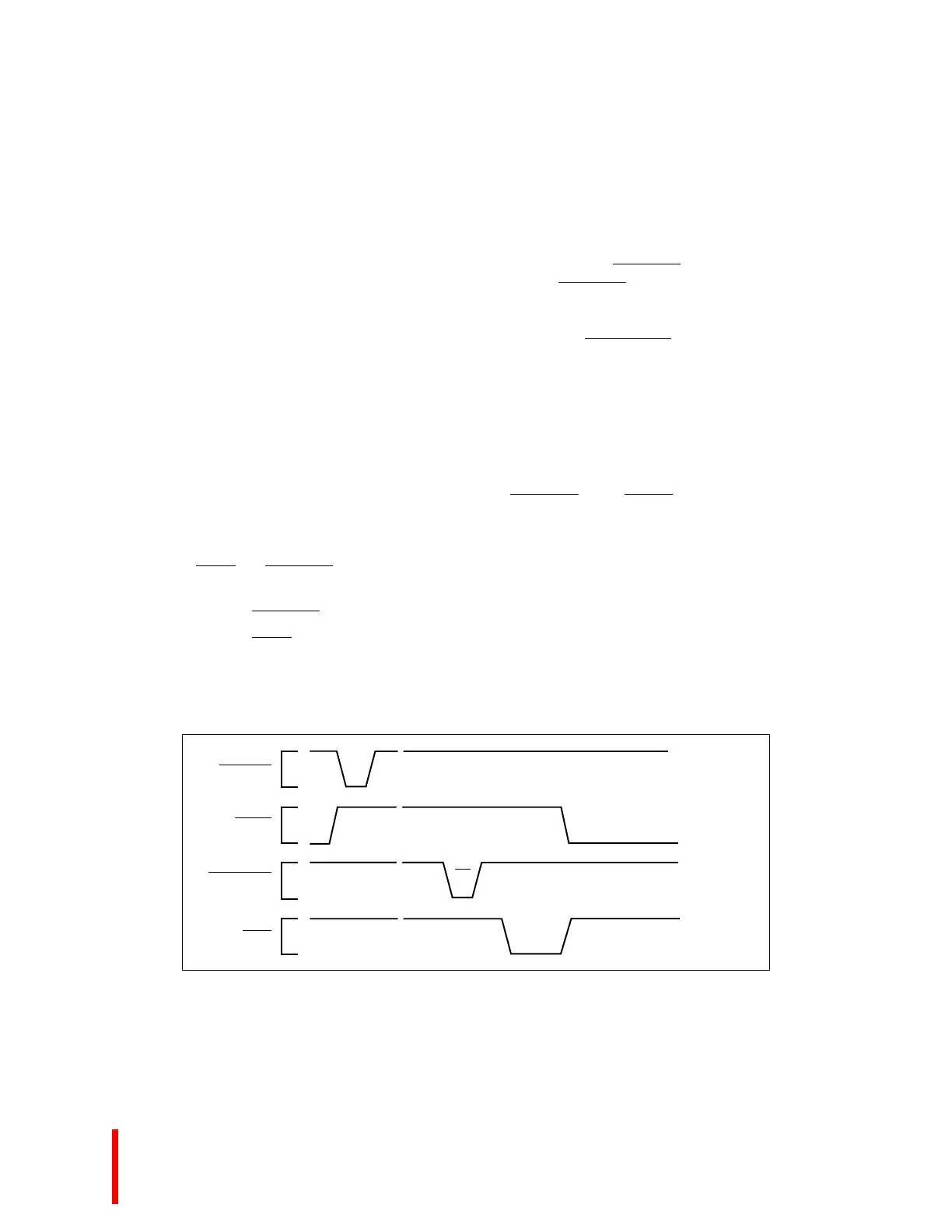
The parallel Centronics interface has eight data lines (PD7:0) and three handshaking lines (PBUSY,
PACK
and PSTROBE). Figure 4-2, Parallel Port Timing Signals, shows the timing relationship between
these signals.
• PSTROBE
falling edge causes data to be latched at the parallel port.
• PACK
is a signal line from the parallel port indicating that data has been received.
• PBUSY is driven to indicate the parallel port is processing the transfer. PBUSY is deasserted
when data is read from the parallel port register.
Figure 4-2. Parallel Port Timing Signals
Parallel port data register Receives parallel data when the PSTROBE
signal is asserted by an
external transmit port. PSTROBE
is used as a latch enable for a
74ABT574 quad-D latch. This register connects to the I/O data bus
as an input-only register. A read to this register causes the I/O
timing control to assert the PPDATA_RD
signal which enables the
data register on the data bus.
Parallel port status register A read-only register used to read the incoming status lines from the
parallel port.
Parallel port control register A write-only register whose outputs directly drive the parallel port
output signals.
PSTROBE
PBUSY
PPDATA_RD
PACK
∼
∼
∼
∼
∼
∼
∼
∼
RD

 Loading...


