A SQUALL II MODULE INTERFACE
5-3
5.2 Power Requirements
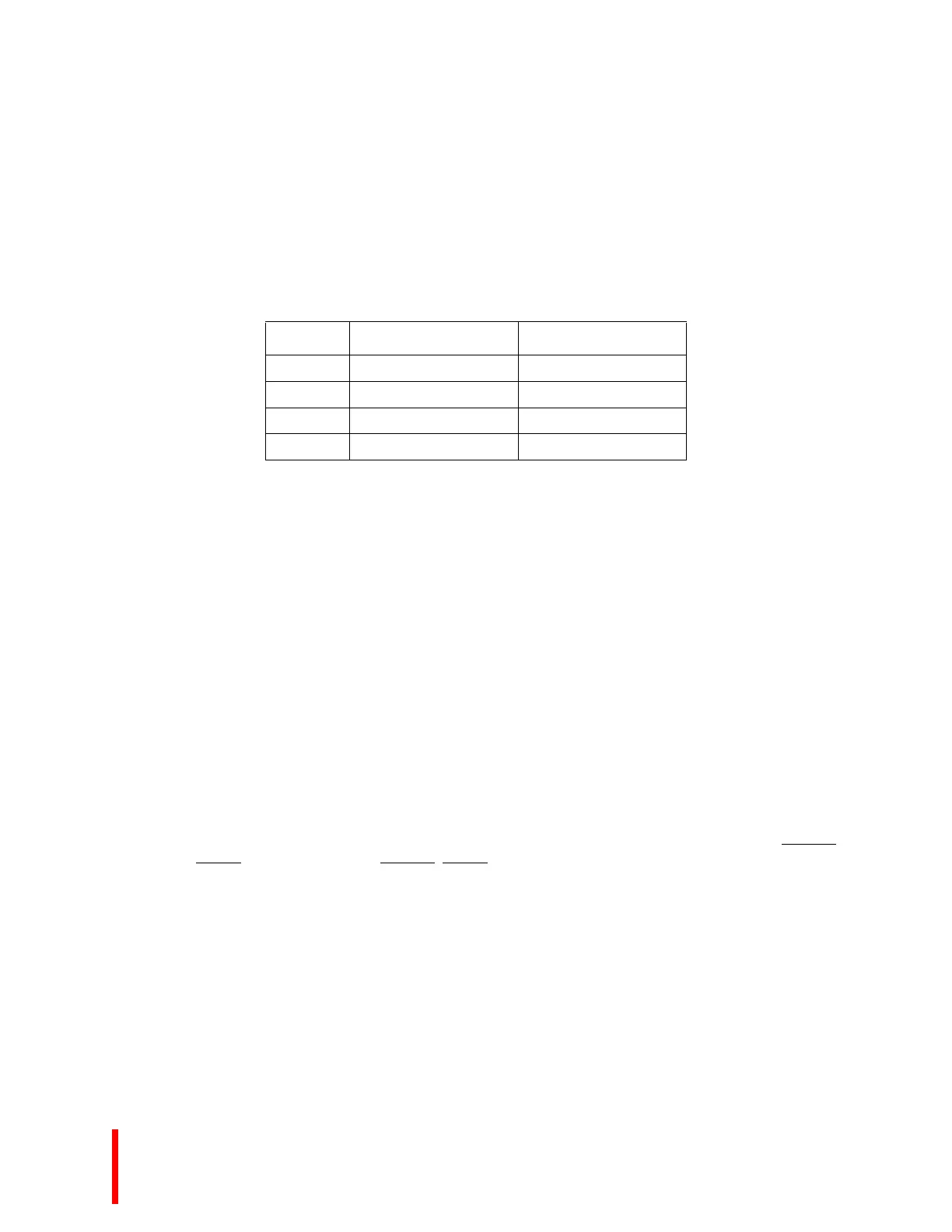
The Squall II Module connectors supply +5v and +12v. Make sure you do not exceed the maximum
amperage listed in Table 5-1. If power is lead off the module via the front panel or the J6/P2 connector,
a fuse should be used to prevent damage to the Cyclone EP that may occur due to an incorrect
connection.
5.3 Squall II Module Serial EEPROM
Every Squall II Module has a 24C08 serial EEPROM which the host processor uses to:
• identify the type and revision of the installed module
• store any system parameters which might be module-dependent
EEPROMs are read and written serially using parallel port B of the 8536 CIO device. Refer to a 24C08
data sheet for information on how to use the device. Routines are available to access these devices. To
access this code, see Section 1.4, ADDITIONAL INFORMATION (pg. 1-4). Every MON960 ROM for
the Cyclone EP reads the serial EEPROMs to properly configure the board.
The first 10 bytes function identically on all Squall II Modules. The remaining memory is assignable by
the module's designer; refer to the particular module's user's manual.
The first four bytes (addresses 0-3) contain the module's region configuration word, stored in little
endian byte ordering (bits 7-0 in address 0).
The next byte (address 4) contains two bits indicating the interrupt detection mode of the Squall II
Module's interrupts. Interrupts are software configurable in the i960 processor’s Interrupt Control
(ICON) Register to be level low activated or falling edge activated. Bit 0 corresponds to SQIRQ0
,
XINT4
. Bit 1 corresponds to SQIRQ1, XINT5. A zero (0) indicates the interrupt is level low activated.
A one (1) indicates the interrupt is falling edge activated.
Bytes 5 and 6 are reserved. Bytes 7 and 8 contain the Squall II Module version number in ASCII.
Users designing their own modules should request a number from Cyclone Microsystems. Refer to
Section 1.4, ADDITIONAL INFORMATION (pg. 1-4) for contact information.
Address 9 contains the module's revision level in binary. This field is assigned and incremented by the
module designer. Bytes 00AH-7FFH are specific to the module. Refer to the processor’s user's manual.
Table 5-1. Power Supply
Volts Squall Connector Pins Maximum Current
+5v 5 pins 2.5 Amps Maximum
+12v 1 pin 0.5 Amps Maximum
-12v 1 pin Not Available
GND 10 pins ----

 Loading...


