EasyManuals Logo

Intel S2600CW User Manual

Intel S2600CW
210 pages
To Next Page IconTo Next Page
To Previous Page IconTo Previous Page
Page #152 background image
Power Supply Specification Guidelines Inte Server Board S2600CW Family TPS
138 Revision 2.4
Table 62. Input Connector and Pin Assignment
Pin
Name
Pin
Name
A1
GND
B1
GND
A2
GND
B2
GND
A3
GND
B3
GND
A4
GND
B4
GND
A5
GND
B5
GND
A6
GND
B6
GND
A7
GND
B7
GND
A8
GND
B8
GND
A9
GND
B9
GND
A10
+12V
B10
+12V
A11
+12V
B11
+12V
A12
+12V
B12
+12V
A13
+12V
B13
+12V
A14
+12V
B14
+12V
A15
+12V
B15
+12V
A16
+12V
B16
+12V
A17
+12V
B17
+12V
A18
+12V
B18
+12V
A19
PMBus* SDA
B19
A0 (SMBus* address)
A20
PMBus* SCL
B20
A1 (SMBus* address)
A21
PSON
B21
12V stby
A22
SMBAlert#
B22
Cold Redundancy Bus
A23
Return Sense
B23
12V load share
A24
+12V remote Sense
B24
No Connect
A25
PWOK
B25
Compatibility Pin*
*The compatibility Pin is used for soft compatibility check. The two compatibility pins are connected directly.
10.3.2.2 Output Wire Harness
The power distribution board has a wire harness output with the following connectors.
Listed or recognized component appliance wiring material (AVLV2), CN, rated min 85°C shall
be used for all output wiring.
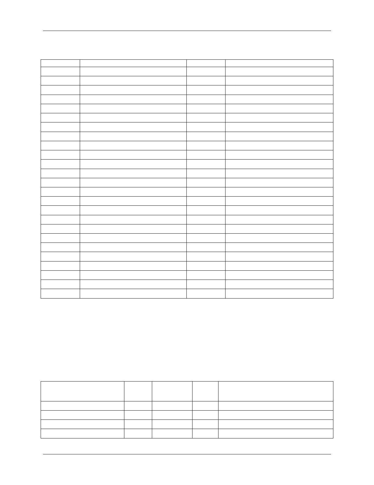
Table 63. PDB Cable Length
From
Length,
mm
To connector
#
No of
pins
Description
Power Supply cover exit hole
280
P1
24
Baseboard Power Connector
Power Supply cover exit hole
300
P2
8
Processor 0 connector
Power Supply cover exit hole
500
P3
8
Processor 1 connector
Power Supply cover exit hole
900
P4
5
Power FRU/PMBus* connector

Table of Contents

Other manuals for Intel S2600CW

Questions and Answers:

Question and Answer IconNeed help?

Do you have a question about the Intel S2600CW and is the answer not in the manual?

Intel S2600CW Specifications

General IconGeneral
BrandIntel
ModelS2600CW
CategoryServer Board
LanguageEnglish

Related product manuals