ENGINE ASSEMBLY II
&3
..*‘\
****I’%,*
‘,
..r’
2.
;
0
;-, ;
5..‘. (g y.:=.
‘*I
\.”
*.,.I...*
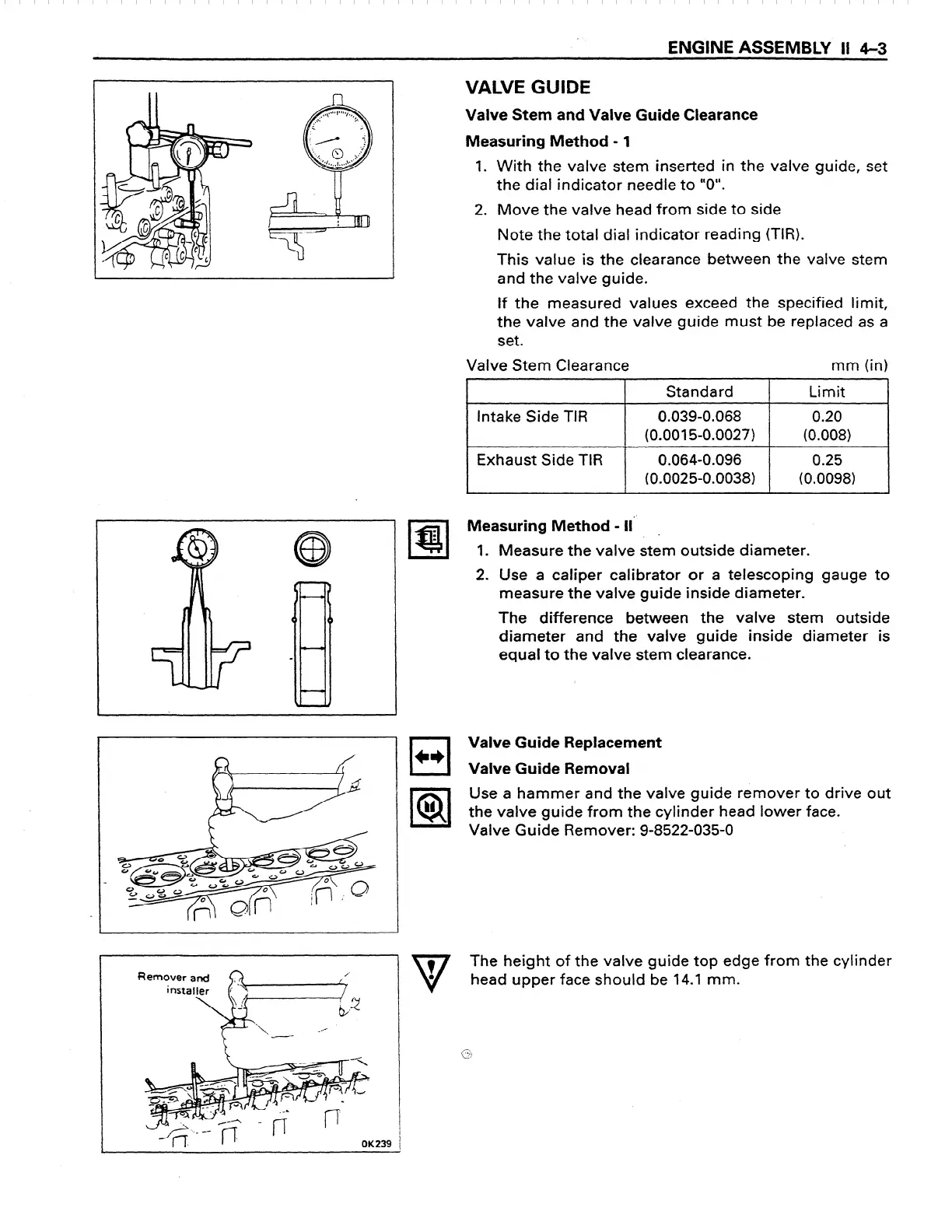
VALVE GUIDE
Valve Stem and Valve Guide Clearance
Measuring Method - 1
1. With the valve stem inserted in the valve guide, set
the dial indicator needle to “0”.
2. Move the valve head from side to side
Note the total dial indicator reading (TIR).
This value is the clearance between the valve stem
and the valve guide.
if the measured values exceed the specified limit,
the valve and the valve guide must be replaced as a
set.
Valve Stem Clearance
mm (in)
*
7
Standard
Limit
Intake Side TIR
0.039-0.068
0.20
(0.001 S-0.0027)
(0.008)
Exhaust Side TIR
0.064-0.096
0.25
(0.0025-0.0038)
(0.0098)
w
4
Measuring Method - II”
-
1. Measure the valve stem outside diameter.
2. Use a caliper calibrator or a telescoping gauge to
measure the valve guide inside diameter.
The difference between the valve stem outside
diameter and the valve guide inside diameter is
equal to the valve stem clearance.
cl
c*
lal
bl
Valve Guide Replacement
Valve Guide Removal
Use a hammer and the valve guide remover to drive out
the valve guide from the cylinder head lower face.
Valve Guide Remover: 9-8522-035-o
/’
/
V
7
The height of the valve guide top edge from the cylinder
0
i2
head upper face should be 14.1 mm.
I f
b
‘1.
-/
--
OK
 Loading...