4-20 ENGINE ASSEMBLY II
C
.
l3il
:
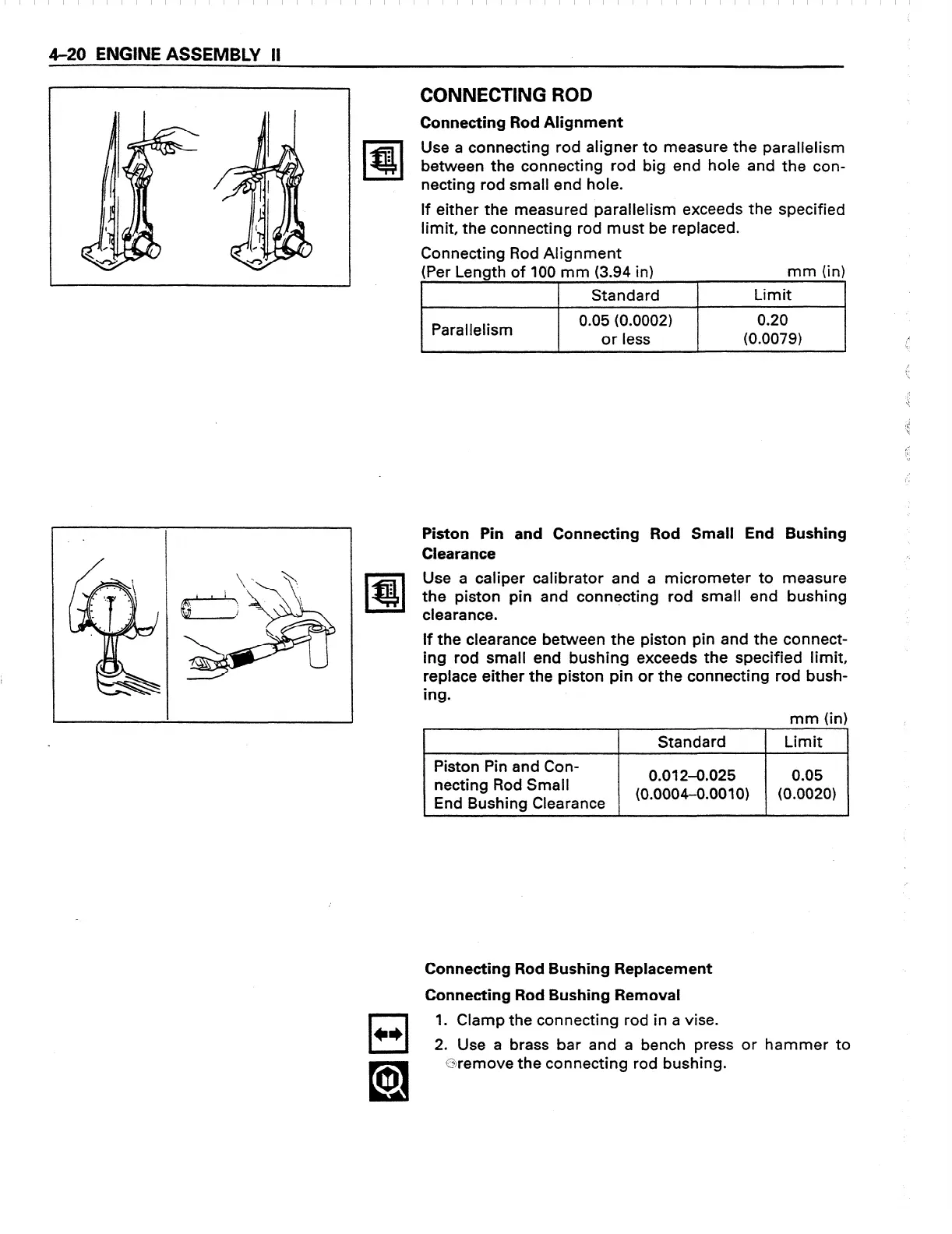
Connecting Rod Alignment
Use a connecting rod aligner to measure
the
parallelism
between the connecting rod big
end
hole and the con-
necting rod small
end
hole.
If either the measured parallelism exceeds
the
specified
limit, the connecting rod must be replaced.
Connecting Rod Alignment
(Per Length of 100 mm (3.94 in)
mm (in)
I I
Standard
I
Limit
I
Parallelism
0.05 (0.0002)
or less
0.20
(0.0079)
Piston Pin and Connecting Rod Small End Bushing
Clearance ‘.
Use a caliper calibrator and a micrometer to measure
the piston pin and connecting rod small end bushing
clearance.
If the clearance between the piston pin and the connect-
ing rod small end bushing exceeds the specified limit,
replace either the piston pin or the connecting rod bush-
ing.
mm (in) I
1 Standard 1 Limit
Piston Pin and Con-
netting Rod Small
0.012-0.025 0.05
End Bushing
Clearance
(0.0004-0.0010) (0.0020)
.
Connecting Rod Bushing Replacement
Connecting Rod Bushing Removal
cl
c*
1. Clamp
the connecting rod
in a vise.
2. Use a brass
bar
and a bench
press or hammer to
@remove the connecting rod bushing.
 Loading...