System-Related Functions
Wiring method:
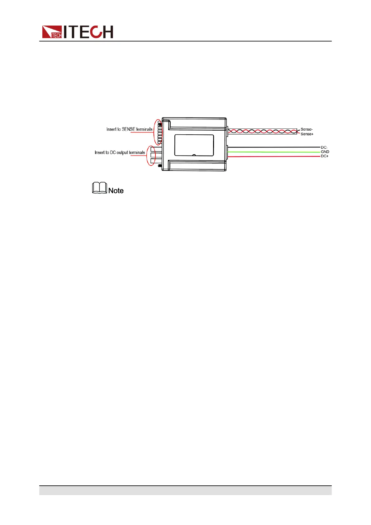
Insert one end of the anti-reverse connection module to the DC output terminal
and sense terminal of the instrument rear panel, and connect the other end to
the test line of the DUT. Introduction of the wiring method:
By default, the DC+/DC- and Sense test lines are not of standard configura-
tion during ex-factory. Please make selection based on the test line specifica-
tions. A set of Sense test line specifications: AWG22-600V; A set of DC+/DC-
test line specifications: AWG12-600V
Usage method:
After the instrument is connected to the anti-reverse connection module, the in-
strument automatically detects the module connection state; if the connection is
succeeded, the SDS module setting in the system menu is defaulted as Enable,
and the anti-reverse connection module is under enabled state. Based on the
user operating state, the module state requirements are as follows:
• When the user conducts common test instead of battery charge/discharge
function, turn on the output, and the instrument panel prompts “SDS En-
abled”. The user needs to set corresponding state of SDS in the system
menu and set the SDS module to Disable state. Otherwise, the instrument
output cannot be turned on.
• When the user enters the battery charge/discharge mode (Function > Bat-
tery), the instrument automatically sets the anti-reverse connection module
SDS in the system menu to Enable state. Under this state, the anti-reverse
connection module can be disabled through manual or command mode.
After the anti-reverse connection module is connected, the user needs to con-
nect the remote measure terminal SENSE+/SENSE-; when the battery charge/
discharge test function (Function > Battery) is executed, the instrument auto-
matically sets Sense to On state in the system menu and detects the SENSE
state; if the connection fails or there is any abnormality, report the protection
prompt that SENSE fails to detect voltage. Press [Esc] to exit.
Copyright © Itech Electronic Co., Ltd.
91

 Loading...


