Inspection and Installation
Name Description
Parity bit None(fixed)
Stop bit 1(fixed)
The operation steps are as follows.
1. Press [Shift]+[P-Set] (System) to enter into the system menu interface.
2. Use left and right keys or rotate the knob to select I/O Config and press
[Enter] key to confirm.
3. Use left and right keys or rotate the knob to select RS485 and press [Enter]
key to confirm.
RS-485 = 9600_8_N_1
4. Rotate the knob to set the baud rate.
5. After finishing the setting, press [Esc] to exit.
2.6.6 CAN Interface
When the optional interface card is RS232+CAN interface (IT-E1207), the
following can help users quickly understand the steps required to connect to the
CAN interface.
The following figure shows the CAN interface system. The user can select the
CAN interface converter to connect to your computer according to the actual
situation. Take the CAN to USB interface device as an example.
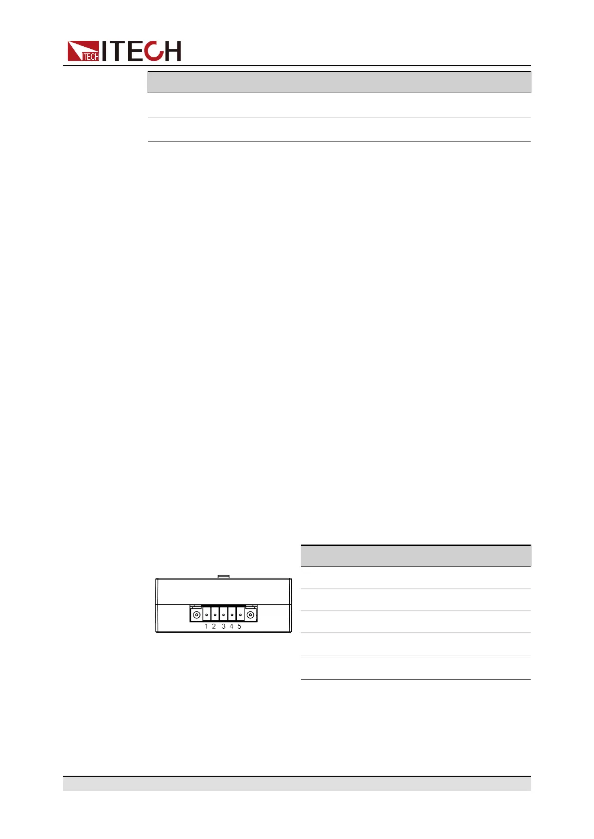
Definition of CAN Pins
The definition of CAN pins are as follows.
Pin Description
IT-E1207
1 TXD,transmit data
2 RXD,receive data
3 GND
4 CAN_H
5 CAN_L
Copyright © Itech Electronic Co., Ltd.
36

 Loading...


