System-Related Functions
The analog signal bandwidth is less than 100Hz, and the signal bandwidth sup-
ports any waveform. When the programmed signal frequency or amplitude ex-
ceeds the output capacity, the instrument will automatically limit the output
amplitude. When the input voltage exceeds 10V, the set value will be limited in
the maximum rated value range.
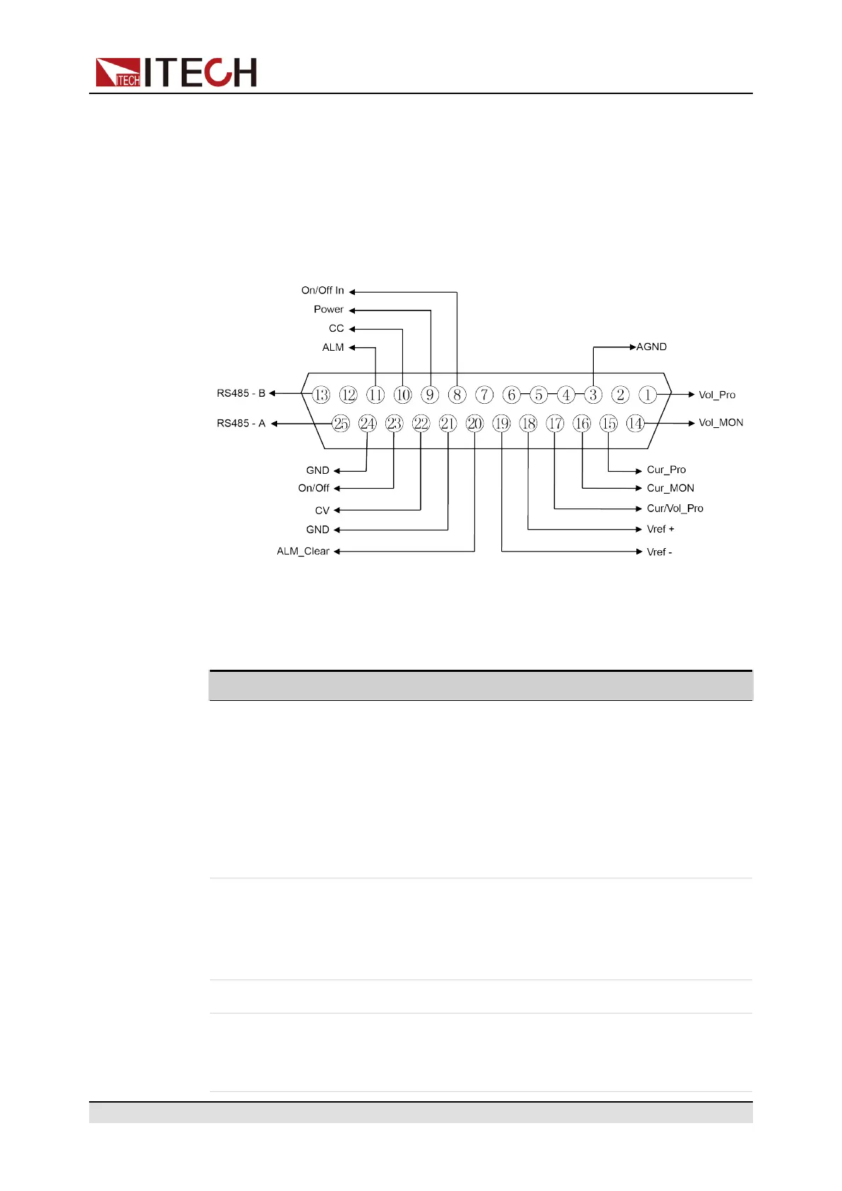
Figure 7–1 DB25 analog interface
Table 7–2 DB25 analog interface description
Pin Name Type Description
1 Vol_Pro Analog
input
• When CV is prioritized, input 0 –
10V voltage value to set the output
voltage between 0 and full scale;
• When CC is prioritized, input 0 –
10V voltage value to set the low
voltage limit (V_low value) between
0 and full scale;
3–6 AGND Ground-
ing of
analog
signal
Grounding of all analog signals, includ-
ing pins: 1 (Vol_Pro), 14 (Vol_MON),
15 (Cur_Pro), 16 (Cur_MON), 17 (Cur/
Vol_Pro), 18 (Vref+) and 19 (Vref-).
2, 7, 12 Unused – –
8 On/Off_ In Digital
input
Control the On/Off state of the instru-
ment. When 0V is input, the instrument
state is switched to Off; when 5V is
Copyright © Itech Electronic Co., Ltd.
84

 Loading...


