Quick start
Copyright © Itech Electronics Co., Ltd. 13
/*Dimmer
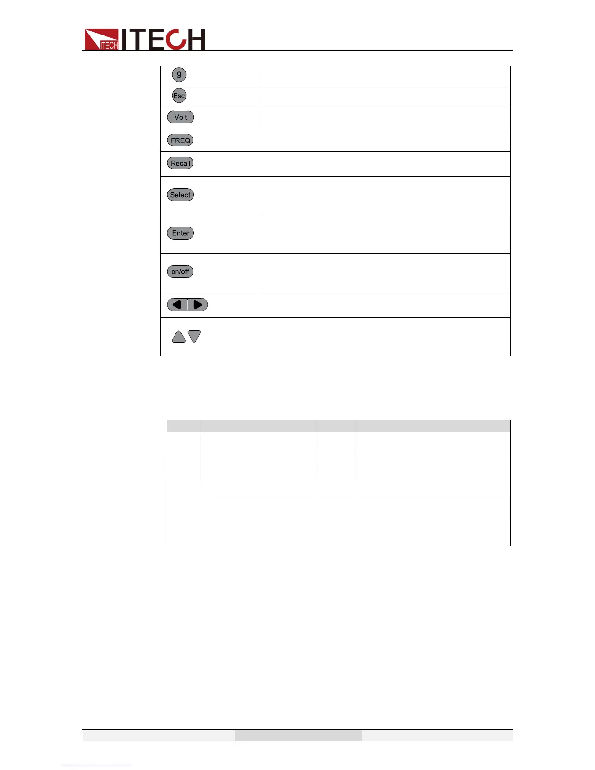
Number 9/Dimmer function key
Cancel /return keys
/High/Auto
Set the voltage value/ Switch the voltage range
between high range and Auto range mode
/Phase
Set the frequency /set the phase angle
/Save
Recall the setup from internal memory/ Store the
AC source settings in non-volatile memory.
Switch the VFD display to be apparent
power,peak current,active power and power
factor/entry the menu setup
Enter key, to confirm the number entered and
trigger button, which is used to trigger
the List test
Output on (off) keys, control power output state /
keypad lock function keys, used to lock the panel
buttons
Left and right direction keys, used to set the value,
to adjust the cursor to the specified location
Up and down keys, used to turnover the item in
the menu or increase (decrease) the output
voltage or current values
2.4 VFD Indicator Description
VFD indicator function description as follow:
OFF
Output is off
Prot
OCP/OVP/OTP/OPP Protection
Rmt
The AC source is in
remote mode
Auto change the voltage
range
Dimmer function is enabled
The power supply
has an error
Shift
Shift button is pressed
Trig
Awaiting for a trigger
signal
Lock
Key operation is locked
2.5 Introduction of rear panel
Rear panel of IT7321

 Loading...