8.2 Oscilloscope Mode
IT7900P series source has the function of displaying the waveform based on
sampling data. The user can select to display or hide the voltage and current
waveform of the input unit. Only the necessary waveform is displayed, which
can facilitate observation. The waveform display interface includes the vertical
axis and horizontal axis.
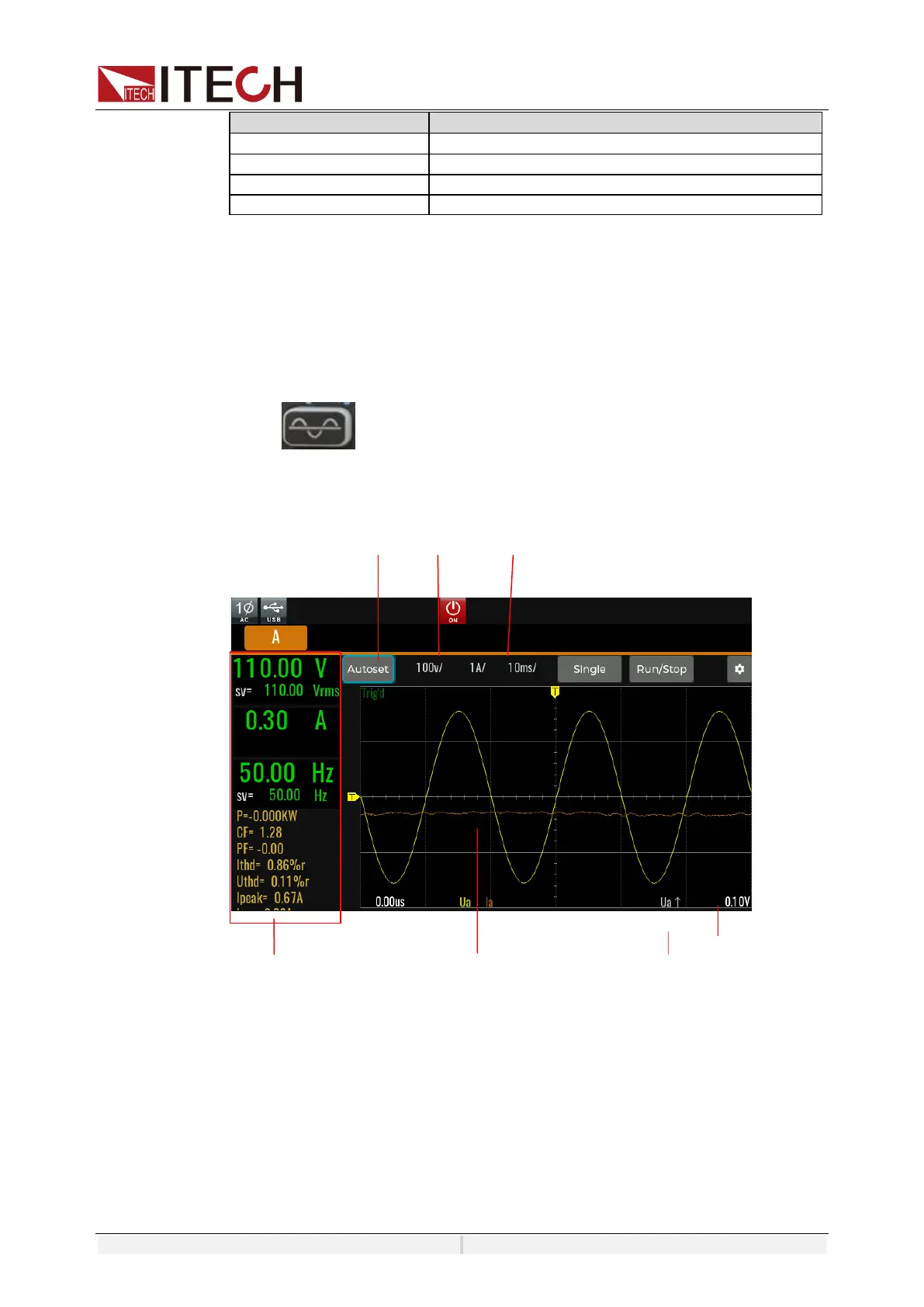
Press on the front panel and the following waveform display interface
will appear. Different modes display different interfaces. the Oscilloscope
interface is shown in the figure below.
Description of keys on the waveform display interface:
Voltage/Current/Time: Adjust voltage/current/time base range
Single: Single measurement key: when single measurement is enabled in the
Stop status, the stop status is enabled again after one measurement based
on the current data updating rate. When single measurement is enabled in
the Ready status, the instrument immediately restarts one measurement
and then enters the Stop status.
Run/Stop: press the corresponding soft key to run or stop the waveform status.
AutoSet: Automatically adjusts the scale of the appropriate vertical axis.

 Loading...