Source Mode Operation
Copyright ©ITECH Electronic Co., Ltd. 62
Trigger1: After clicking Run, wait for the Trigger1 signal to be received to
start executing sampling.
Trigger2: After clicking Run, wait for the Trigger2 signal to be received to
start executing sampling.
Capture-Vac: The voltage signal sampling after compared. When this mode
is selected, additional parameters need to be set.
⚫ Trigger delay: Set the sample data delay time. Set a positive value to record
data after the capture event occurs. A negative value means that data before
the capture event occurs is recorded.
⚫ Compare: Select the object of comparison, either Vac/Rms or Vac/Peak
⚫ Up Limit: AC voltage upper limit value, grid voltage greater than the upper
limit value will start sampling.
⚫ Down Limit: AC voltage lower limit value, grid voltage less than the lower
limit value will start sampling.
⚫ Display mode: Auto/Normal
5.16 Voltage Signals Simulation
In AC mode or AC+DC mode, users can import TDMS waveform curve files for
simulation, and set parameters such as repetition times and waveform offset for
imported waveform.
By default, the open waveform is only for real-time simulation. If you remove the
USB disk, the waveform disappears. Users can also permanently save the open
waveform to the power supply memory.
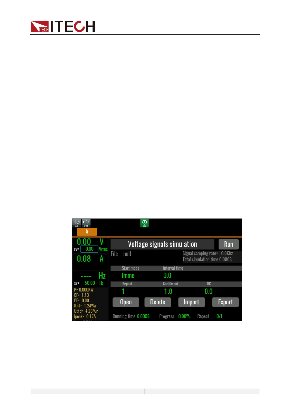
Directly click Simulation in the Menu to enter the voltage signal Simulation
interface, as shown below:
Start mode: can be selected as immediate execution or trigger execution.
Interval time: The interval between waveform repeats.This parameter is
displayed only when start mode is selected for Imme.
Repeat: Number of repeated execution of waveform
Coefficient: Waveform amplification Coefficient
DC: DC offset

 Loading...