Inspection and Installation
Copyright © Itech Electronic Co., Ltd. 9
Steps
1. Check whether the power switch of the instrument is turned OFF.
2. Connect one end of the power cord to the AC input connector on the rear
panel of the instrument.
3. Connect the other end of the power cable to the socket configured with
protective earth.
1.7 Connect the Device Under Test (DUT)
Before connecting the DUT
To prevent electric shock and damage to the instrument, observe the following
precautions.
Before connecting the DUT, turn off the power of the test loop to avoid the
risk of electric shock during connection.
To avoid electrical shock, before testing, please make sure the rating
values of the testing cables, and do not measure the current that higher
than the rating value.
Always use test cables provided by ITECH to connect the equipment. If
test cables from other factories are used, please check that the test cable
can withstand maximum current.
Specification
Test cables are not standard accessories of the instrument. Please select
optional red and black test cables for individual sales based on the maximum
current value. For specifications of test cables and maximum current values,
refer to “Specifications of Red and Black Test Lines” in “Appendix”.
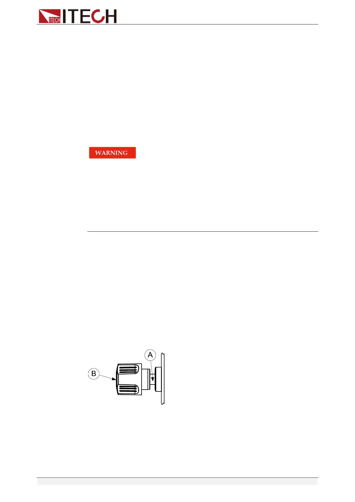
Introduction of Binding Posts
The IT8500+ series (except IT8516C+) load front panel contains the following
terminals and the maximum rated current of the terminal at position (A) is the
maximum rated input current of the instrument. Securely fasten all wires by
hand-tightening the binding posts. You can also insert standard banana plugs
into the front of the connectors as shown in (B), and the maximum rated current
at (B) is 10 A.
Local measurement
1. Check whether the power switch is in Off position.
2. (Optional) Unlock the load input terminal cover.
3. Unscrew the screws of the input terminals. Connect the red and black test
cables to the input terminals. Re-tighten the screws.
When maximum current that one test cable can withstand fails to meet the
 Loading...


