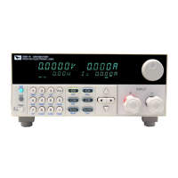
Functions and Characteristics
Copyright © Itech Electronic Co., Ltd. 24
When the [On/Off] button light is off, the lower left of the VFD displays OFF,
indicating that the input is turned off.
3.4 Key Lock Function
Press the combined keys [Shift] +[On/Off] (Lock) to lock the front panel keys,
and VFD will display a Lock label. In this functional state, all keys except the
following keys are invalid. Pressing [Shift] +[On/Off] (Lock) again will cancel
the lock.
The [On/Off] button is available to toggle the input on and off.
The combined keys [Shift]+[7] (Info) is available to view the instrument
information. When viewing the instrument information, press [Esc] to exit.
3.5 Short-circuit Analog Function
Short circuit simulation and short circuit current measurement: you may press
[Shift] + [1] (Short) button to emulate a short state. It can be used to check
whether the tested instrument’s short protection is available.
Press [Shift] + [1] (Short) to switch the short circuit condition. The short-circuit
operation does not affect the current set value. When you press [Shift] + [1]
(Short) again, the electronic load returns to the original setting state.
In the short-circuit status, the actual consumed current value depends on the
operating mode and current range of the load. In CC, CW and CR modes, when
the current is within the maximum range, the short-circuit current is the input
current value. When the current exceeds the maximum range, the maximum
short-circuit current is 110% of the range. In the CV mode, the short circuit is
equivalent to setting the constant voltage value of the load to 0V.
3.6 System Menu (System)
Press [Shift] + [ 8 ] (system) to enter the system menu.
The value modified with knob during operation will be
saved after input is off. For example, the DC load is set
to 1A by press [CC] and turned on the input. Then
increase the setting value to 2A with knob. When
customer turn off input, the setting value is still 2A.
 Loading...


