Inspection and Installation
Copyright © Itech Electronic Co., Ltd. 12
Figure 1-6 Connecting AC Input
1.6 Connecting the Device Under Test
The instrument supports two connection methods between electronic load and
DUT: Local measurement and Remote sensing.
⚫ Local measurement:The voltage sensed by the instrument is the voltage at
the output terminal of the instrument.
⚫ Remote sensing:The voltage sensed by the instrument is the voltage at the
terminal of the remote object under test.
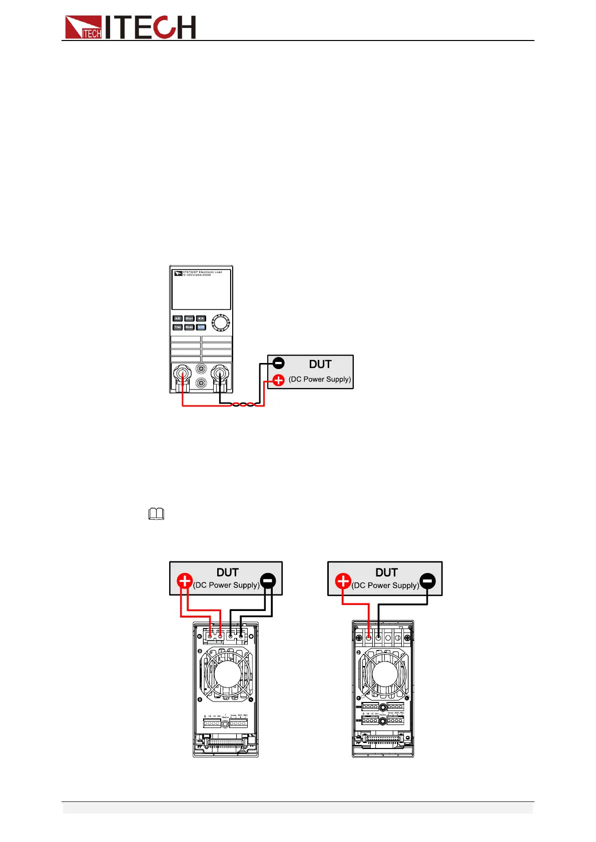
Connecting the DUT (Local Measurement)
The connection diagram and steps of local sensing are as follows:
⚫ Front panel terminal wiring
1. Before connecting the DUT, be sure that the Mainframe Power is in Off
position.
2. Loosen the input terminals and connect the red and black test cables
to the input terminals. Re-tighten the terminals.
3. Directly connect the other end of the red and black cables to the DUT.
Note
Only the IT8731P/IT8732P/IT8732BP/IT8733P/IT8733BP/IT8722P/IT8723P/IT8722BP
modules support front panel terminal wiring.
⚫ Rear panel terminal wiring
(Single channel modules) (Double channel modules)
 Loading...


