Quick Start
Copyright © Itech Electronic Co., Ltd. 19
1. VFD display
2. Module keyboard: <A/B>,<Short>,<Tran>,<Mode>,<On/Off> and direction
keys.
3. Knob, change parameters
4. Mainframe function keyboard: control each channel’s operating status. Control
input status: On/Off. Specific buttons: <Chan>, <Save>, <Recall>, <Setup>,
<On/Off>, <Trig>, <Start>, <Pause>, <Enter>, <Shift>, <▲>, <▼>.
5. Mainframe compound button((numeric keys):1.set parameters 2.assembled
menu function. detailed buttons:<1>,<2>,<3>,<4> plus function keys to enter
the system menu,<5> plus function keys to enter the config menu, <6> plus
function keys to enter program menu,<7> plus function keys to select local
operation,<8> plus function keys to select lock function, <9>, <0>,<.>, <Esc>.
6. Power switch ON/OFF
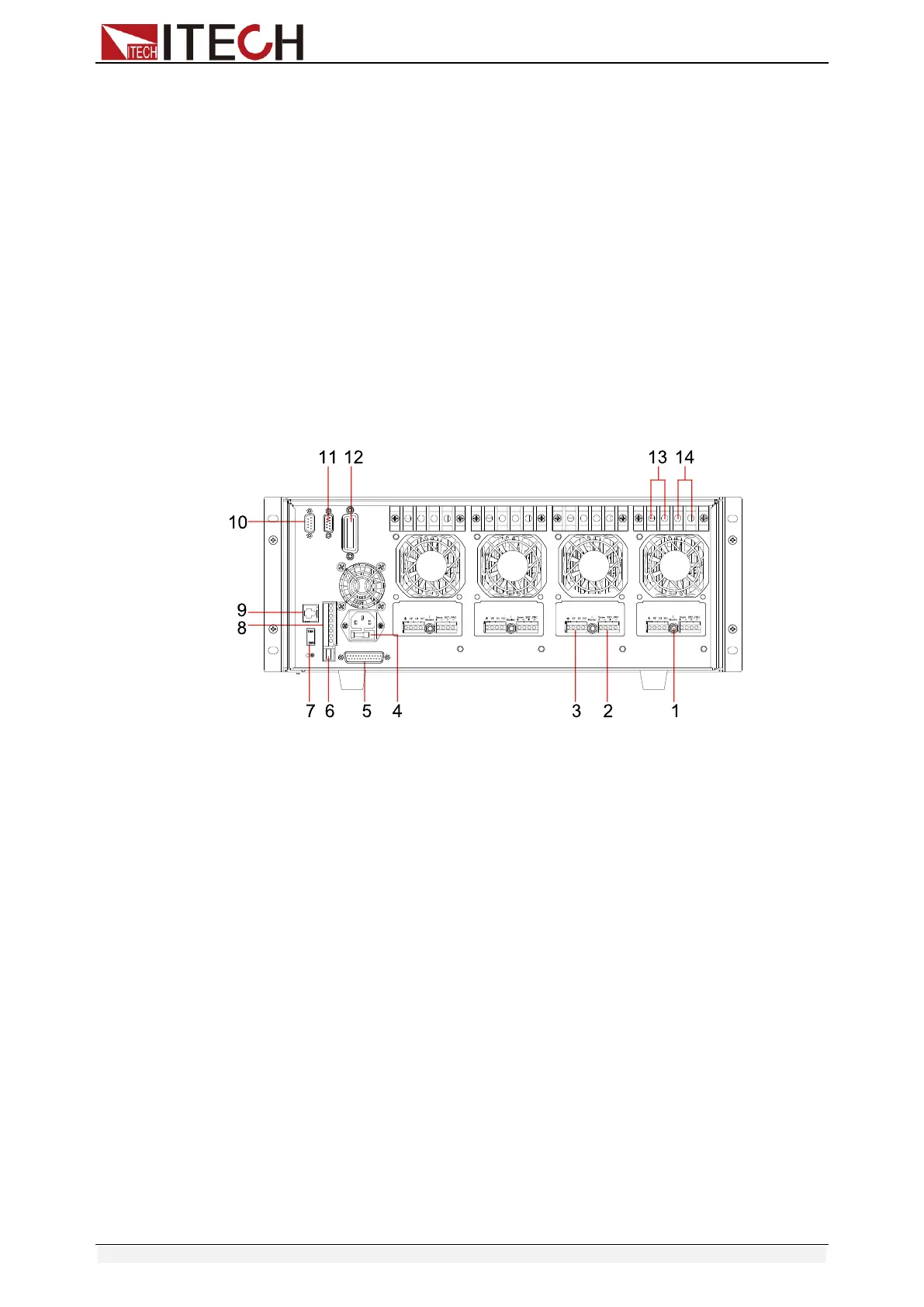
2.4 Rear panel description
The part introduces the location of terminals and interfaces on the rear panel.
Refer to figure 2-2 for more details.
Figure 2-2 IT8700 rear panel (take example of IT8702)
1. Current monitoring terminal
2. Remote sense and external input control terminal
3. Digital I/O and VF output signal terminal
4. Power input socket (fuse contained)
5. Extended module interface
6. USB communication cable interface
7. Input voltage level switch(110V/220V)
8. Trigger input /output and ON/OFF input/output interface
9. Network interface
10. 9-pin COM port interface connector(RS232 communication cable interface)
11. 9-pin COM serial port connector(extended keyboard interface )
12. GPIB interface(Only for IT8700(G) series.)
13. Positive input terminal of module (if module is dual-channel, there is one
positive terminal and one negative terminal)
14. Negative input terminal of module (if module is dual-channel, there is one
positive terminal and one negative terminal)
2.5 Power-on Selftest
A successful test process indicates that the instrument meets the factory
specifications and can be operated well. Before operation, please confirm that
you have fully understood the safety instructions.
 Loading...


