Regulations
AirModule –6 720 813 268(2014/10)
13
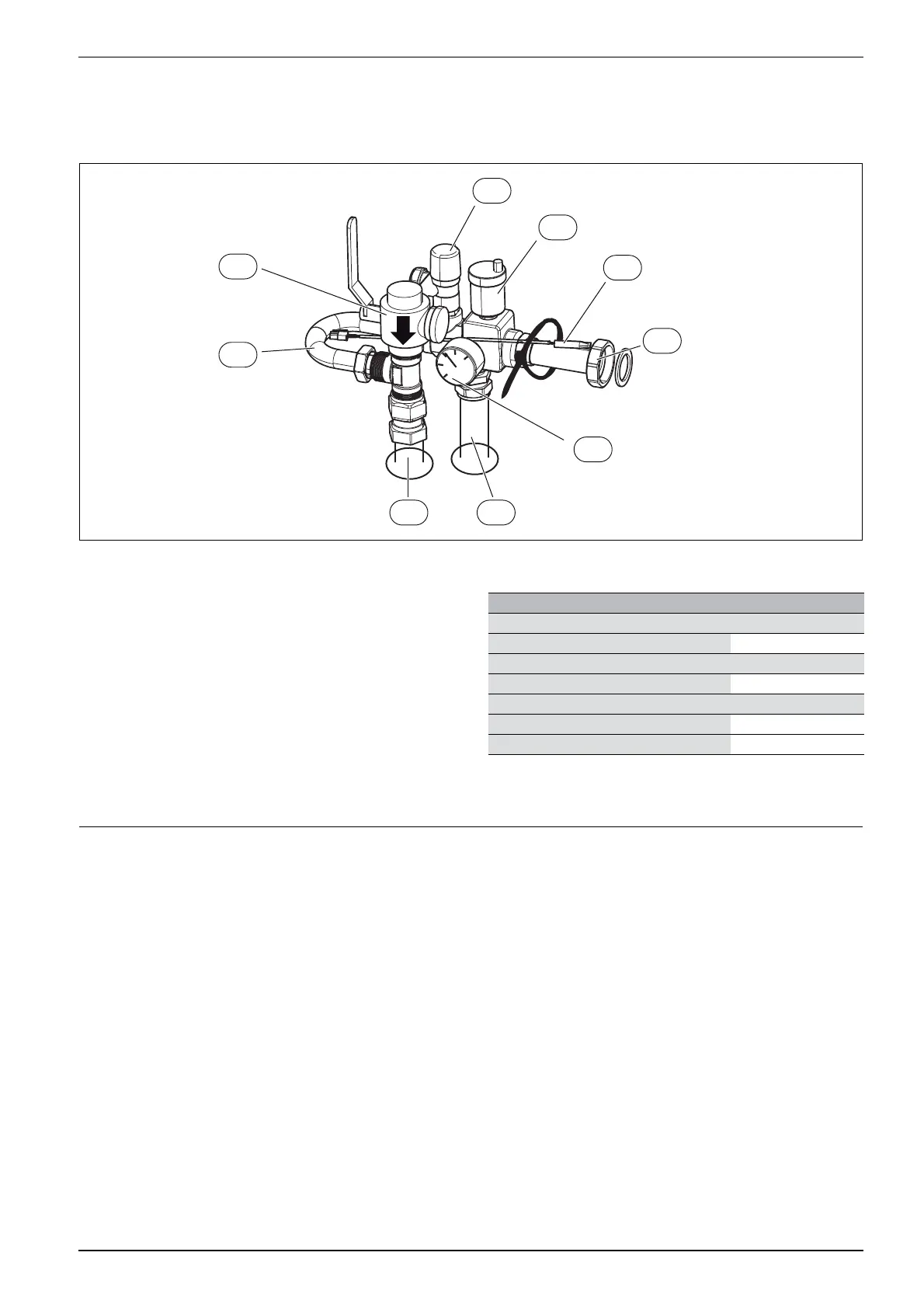
Assemble the safety assembly:
▶ First install the particle filter ([SC1], figure 10) on the T-unit.
▶ Install the other parts, but do not tighten the nuts completely on the
bypass ([4], figure 10).
▶ Place the flow temperature sensor in the sensor pocket ([T0],
figure 10), and secure the sensor with a cable tie.
▶ Fit the safety assembly on the heat pump module.
▶ Tighten the nuts completely on the bypass ([4], figure 10).
Fig. 10 Safety assembly fitted
[1] Circulation pump heating system connection (PC1), G1
½ (40R) adapter to heating system flow
[2] Flow to safety group
[3] Return from safety group
[4] Bypass
[SC1] Particle filter, connection G1internal thread from heating
system return
[FC1] Pressure relief valve
[VL1] Automatic air vent valve
[T0] Flow temperature sensor
[GC1] Pressure gauge
5.2 Pipework
6 Regulations
The following regulations and requirements must be observed:
• Local rules and regulations, including special rules, of the
responsible power supply company
• National building regulations
• EN 50160 (Voltage properties in power grids for public distribution)
• EN 12828 (Heating systems in buildings - Design and installation of
water-based heating systems)
• EN 1717 (Water supply - Protection against pollution of potable
water)
6 720 809 156-13.3I
FC1
VL1
T0
1
GC1
23
4
SC1
Pipe dimensions (mm) Heat pump module
Heating installation
Spring clip connection Cu Ø 28
1)
1) See Connections in safety assembly
Cold and hot water
Stainless spring clip connection Ø 22
Heat transfer medium
Spring clip connection Cu Ø 28
Leakage drain water/drain in both Ø 32
Table 8 Pipe dimensions
 Loading...


