Installation
AirModule –6 720 813 268(2014/10)
17
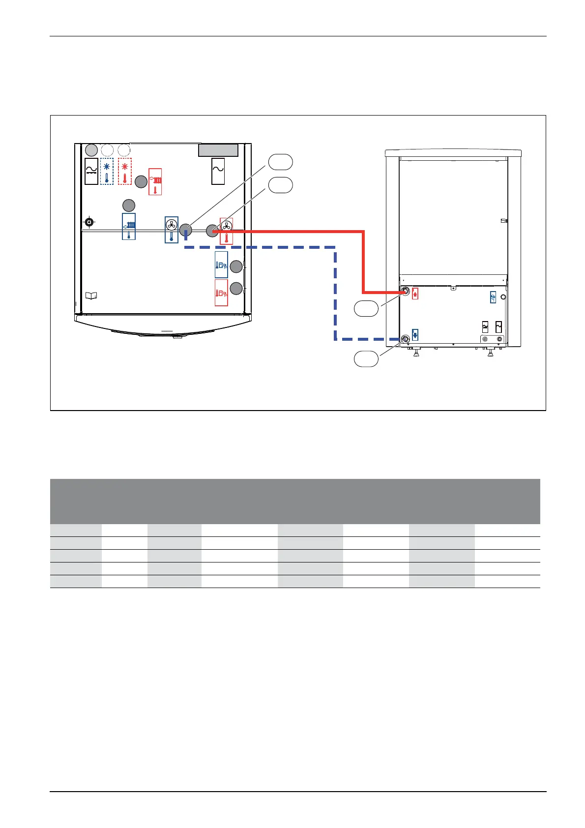
7.11 Connecting the heat pump module to the heat pump
Insulate pipes and connections against condensation if cooling is to be
used.
▶ Select pipe size according to table 11.
▶ Connect the return to the heat pump [4] to the heat transfer medium
out [1] figure 13.
▶ Connect the flow from the heat pump [3] to the heat transfer medium
in [2] Figure 13.
Fig. 13 Heat pump connections heat pump module
[1] Heat transfer medium out (to the heat pump)
[2] Heat transfer medium in (from the heat pump)
[3] Flow from heat pump
[4] Return to heat pump
6 720 809 156-14.1I
<50V 230V
/
400V
<50V
230V
/
400V
1
2
4
3
Heat pump
output (kW)
Heat
transfer
fluid delta
(K)
Nominal flow
(L/s)
Maximum pressure
drop (kPa)
1)
1) For pipes and components between the heat pump module (indoor unit) and heat pump (outdoor unit).
AX20
inner-Ø 15 (mm)
AX25
inner-Ø 18 (mm)
AX32
inner-Ø 26 (mm)
AX40
inner-Ø 33 (mm)
Maximum pipe length PEX (m)
550.32 68 28 60
750.33 55 14 33 60
950.43 40 82160
13 5 0.62 56 14 60 60
17 5 0.81 18 15 60
Table 11 Pipe dimensions and max. pipe length for connection of heat pump to heat pump module
 Loading...


