Electric installation
AirModule –6 720 813 268(2014/10)
31
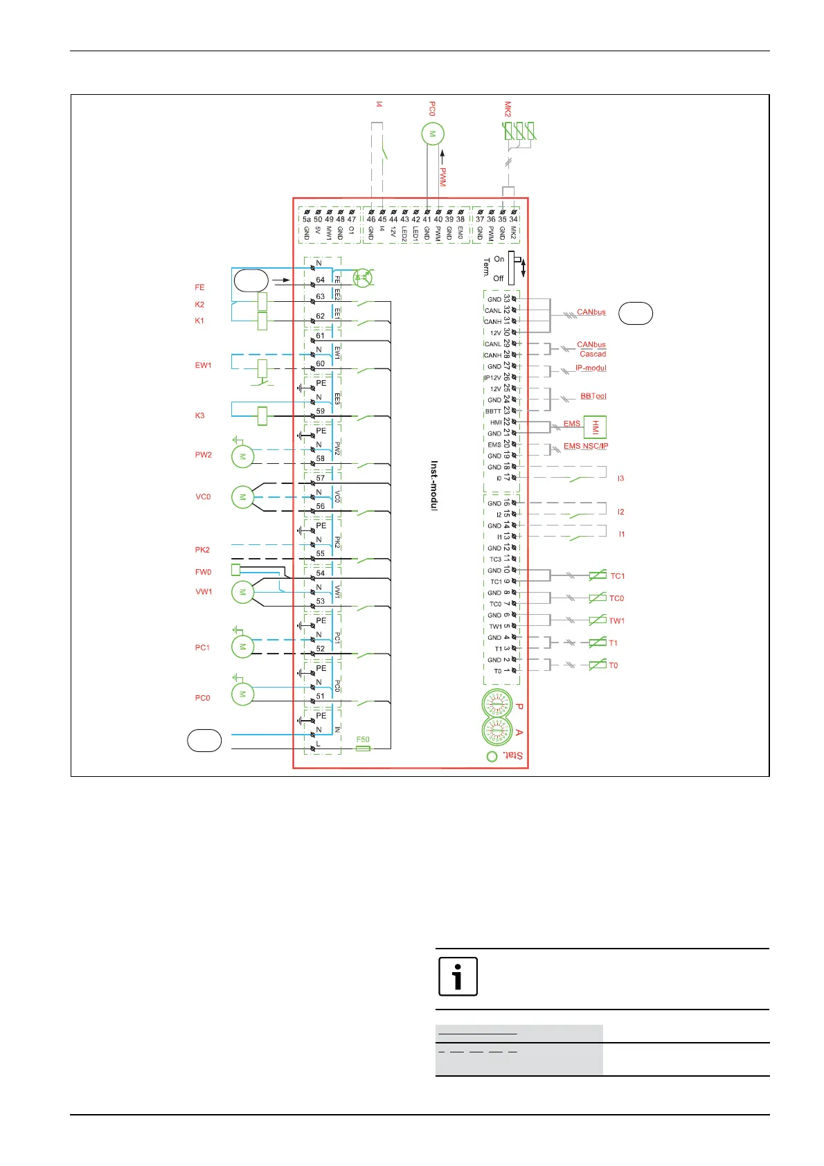
8.10 Installer module circuit diagram
Fig. 31 Installer module circuit diagram
[I1] External input 1
[I2] External input 2
[I3] External input 3
[I4] External input 4
[MK2] Condensation sensor
[PC0] Circulation pump PWM signal
[T0] Flow temperature sensor
[T1] Outside temperature sensor
[TW1] DHW temperature sensor
[TC0] Return heat transfer medium temperature sensor
[TC1] Flow heat transfer medium temperature sensor
[EW1] Immersion heater start signal in hot water cylinder (external)
[FE] Overheating protection alarm
[FW0] Anode 230 V (accessories)
[K1] Immersion heater contactor EE1
[K2] Immersion heater contactor EE2
[K3] Immersion heater contactor EE3
[F50] Fuse 6.3 A
[PC0] Heat transfer medium circulation pump
[PC1] Heating system circulation pump
[PK2] Cooling season relay output 230 V
[PW2] Hot water DHW circulation pump
[VC0] Recirculation exchange valve
[VW1] Heating/DHW exchange valve
[1] 230 V~ operating voltage ([5] Fig. 30 or [4] Fig. 29)
[2] Immersion heater/pressure switch alarm output ([4] Fig. 30
or [3] Fig. 29)
[3] CAN BUS to heat pump (I/O module card)
6 720 809 156-15.2I
1
3
2
Relay output max. load PK2: 2 A, cos>0.4. Higher load
requires installation of an intermediate relay.
Delivered connected
Connected during installation/
accessories
 Loading...


