Troubleshooting
AirModule 6 720 813 268(2014/10)
56
A51 6021 Defect collector temperature
sensor
Check configuration. The selected setting requires a collector
sensor.
Modify configuration.
Check the connecting cable between the solar module and the
collector sensor.
Establish a correct connection.
Check the collector sensor according to the diagram. Replace the sensor if the values are incorrect.
Check the collector sensor connecting terminal voltage on the
solar module according to the diagram.
If the sensor values are correct but the voltage is
incorrect, the solar module should be replaced.
A51 6022 Cylinder 1 bottom temperature
sensor defect
Standby mode active
Check configuration. The selected setting requires a bottom
buffer cylinder sensor.
Modify configuration.
Check the connecting cable between the solar module and the
bottom buffer cylinder sensor.
Establish a correct connection.
Check the connecting cable electrical connection to the solar
module.
Tighten screws or connections.
Check the bottom buffer cylinder sensor according to the
diagram.
Replace the sensor if the values are incorrect.
Check the buffer cylinder sensor connecting terminal voltage on
the solar module according to the diagram.
If the sensor values are correct but the voltage is
incorrect, the module should be replaced.
A61
A62
A63
A64
1081
1082
1083
1084
Two master user interfaces in the
system.
Check the installation level parameters.
(Several user interfaces besides HPC400 have been configured
as REGO in the BUS system)
Register the user interface as Master for heating
circuit 1 to 4.
(Configure CR10 as remote control)
H01
A61
A62
A63
A64
5203 Alarm E10 outside temperature
sensor T0 error
(A61 = Heating circuit 1;
A62 = Heating circuit 2;
A63 = Heating circuit 3;
A64 = Heating circuit 4)
Check the connecting wire between the user interface and the
outside temperature sensor.
If there is no connection, correct the error.
Check the connecting cable electrical connection to the outside
temperature sensor and/or the user interface terminal.
Clean corroded terminals in the outside temperature
sensor assembly.
Check the outside temperature sensor according to the
diagram.
Replace the sensor if the values are incorrect.
Check the outside temperature sensor connecting terminal
voltage on the user interface according to the diagram.
If the sensor values are correct but the voltage is
incorrect, the user interface should be replaced.
H01 5239 DHW temperature sensor alarm
TW1 error
If no DHW function is required,
the DHW system should be
deactivated in the user interface.
No DHW system installed Deactivate the DHW system in the service menu
Check the connecting wire between the user interface and the
DHW temperature sensor.
If it is defect, the sensor should be replaced.
Check the connecting cable electrical connection to the user
interface.
Tighten screws or plugs if they are loose.
Check the DHW temperature sensor according to the diagram. Replace the sensor if the values are incorrect.
Check the DHW temperature sensor connecting terminal
voltage on the user interface according to the diagram.
If the sensor values are correct but the voltage is
incorrect, the user interface should be replaced.
H01
A41
5284
4051
Warning: Last thermal
disinfection failed
Check for leakage or if water is possibly being drawn from the
water heater constantly due to taps being open.
Stop such continuous hot water consumption, or
change the time for thermal disinfection.
Check the DHW temperature sensor position. It might be
incorrectly installed or hanging in the air.
Position the DHW temperature sensor correctly.
Check if the heating loop in the cylinder has been completely
vented.
Vent if required.
Inspect the connecting pipes to the cylinder and check that they
are connected correctly.
Correct possible errors in the pipework.
Check if the installed DHW circulation pump capacity is
sufficient.
If there are errors, the pump should be replaced.
Excessive DHW circulation pipe loss Check the DHW circulation pipes
Check the DHW temperature sensor according to the diagram. If the sensor values do not correspond with the
diagram values, it should be replaced.
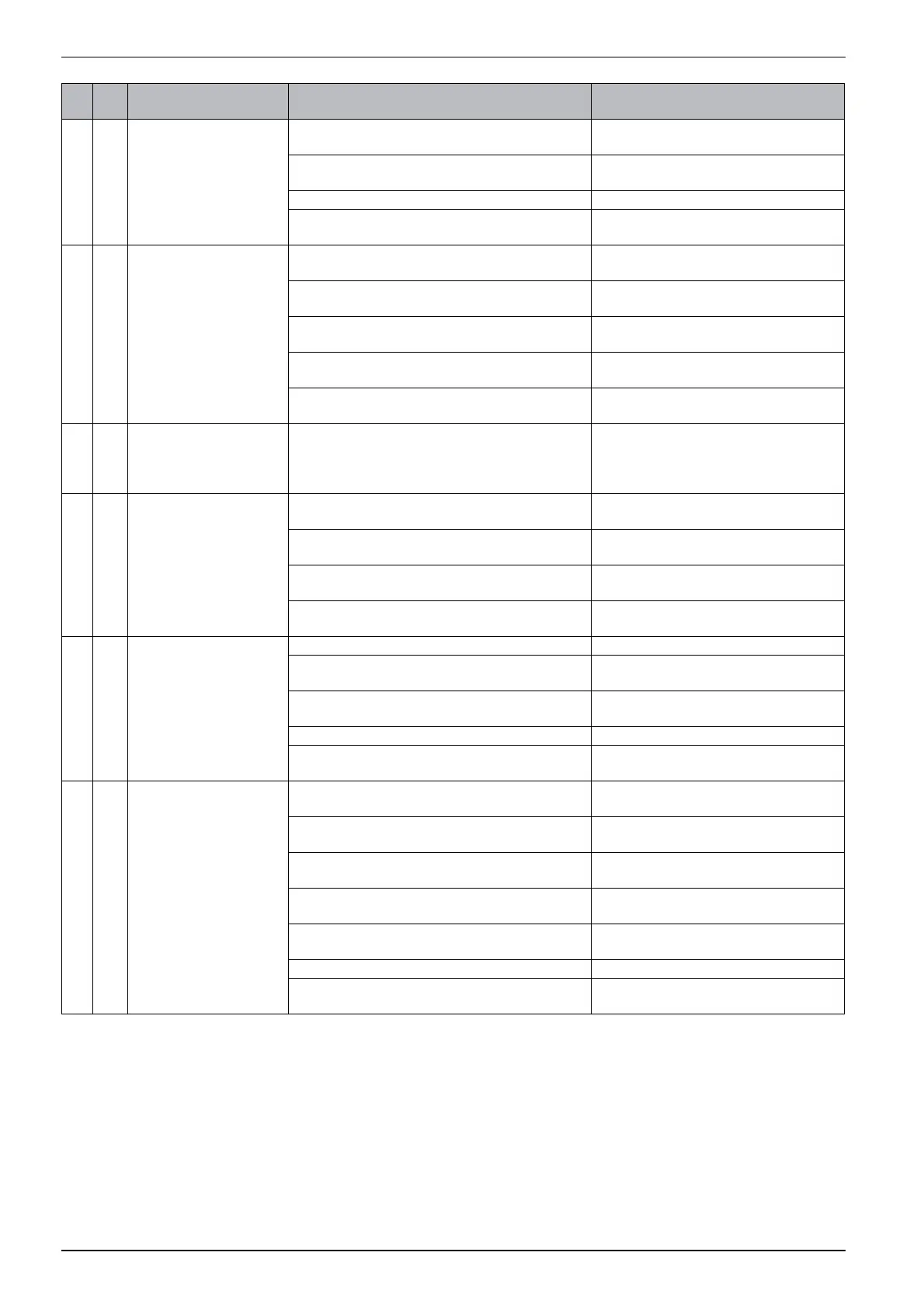
Error
code
Sub
code
Cause or error description Test procedure/cause Solution
Table 41 Error messages
 Loading...


