Technical Data and Specifications 6-1
Revision 2 - 26 April, 2000 HP SERIES DIMMER TECHNICAL MANUAL
6.0 Disassembly
Should it become necessary to repair or replace a PCB, the following procedures should
be used. The numbers below refer to the sequence of operations.
6.1 CPU card removal
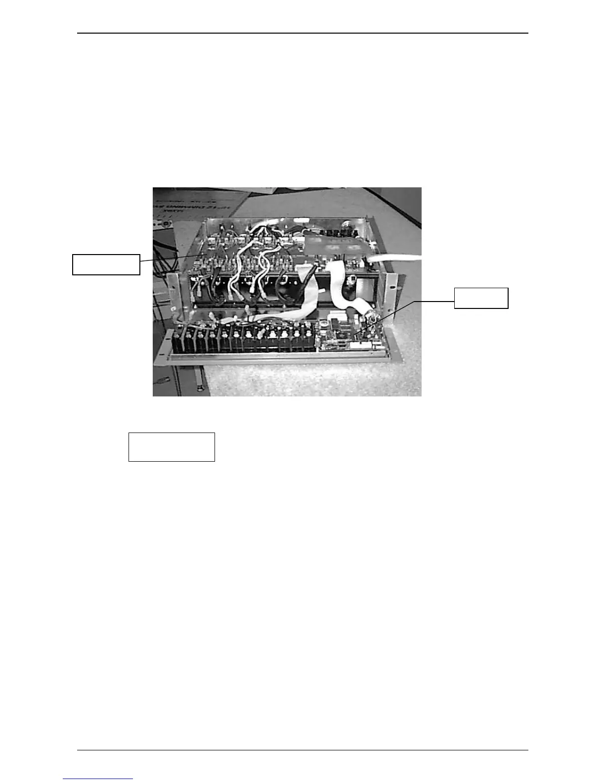
Figure 6.1 HP12-TR with CPU card exposed
*
Figure 6.1
1.
Remove the sixteen lid screws and the lid.
2.
Remove the screws holding the front panel in place (3 underneath, 2 pairs each
side).
3.
Pull the front panel assembly forward and disconnect the wires to the circuit
breakers.
4.
Remove the front panel assembly from the chassis.
5.
Disconnect the flat cables from the CPU card to the Front Panel card and the Output
card. Unplug the DMX connector lead.
6.
Undo the five CPU card mounting screws.
7.
The CPU card can now be removed.
Re-assembly involves carrying out the above operations in reverse order.
CPU CARD
OUTPUT CARD
 Loading...